

Weebo Assembly Pt 2
If you did not make the screen lid yet, lets do that. Take the two printed parts and glue them together. Of course using super glue, sanding, filler putty and primer get it nice and smooth and painted. Do the same for the Screen Bezel. (Note that this part may be different depending on what LCD you end up getting. But it should work for any of the 6.2-6.4″ 4:3 LCD screens.
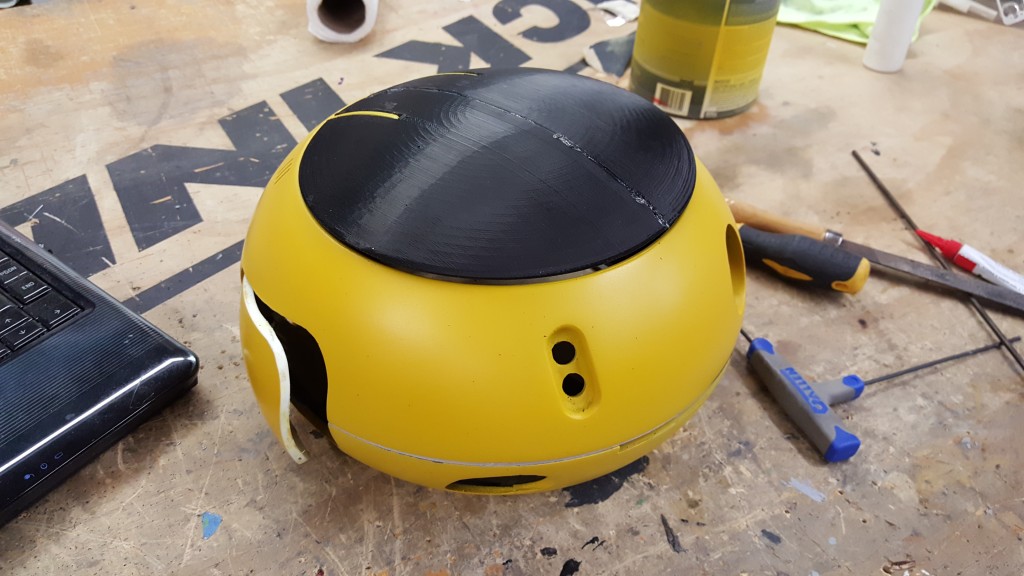
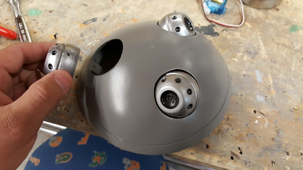
We can also get the ears mounted to the base. It may take some test fitting and sanding to get them to fit right, but it should be pretty close from the start. I used a small 6-24 screw and a couple washers to give it a good tight fit but still allowed movement.
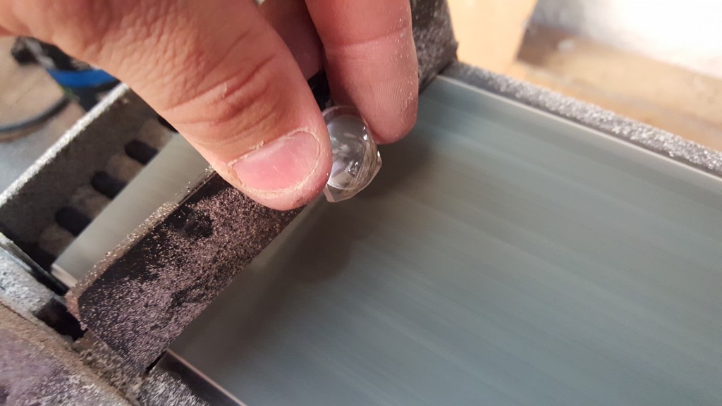
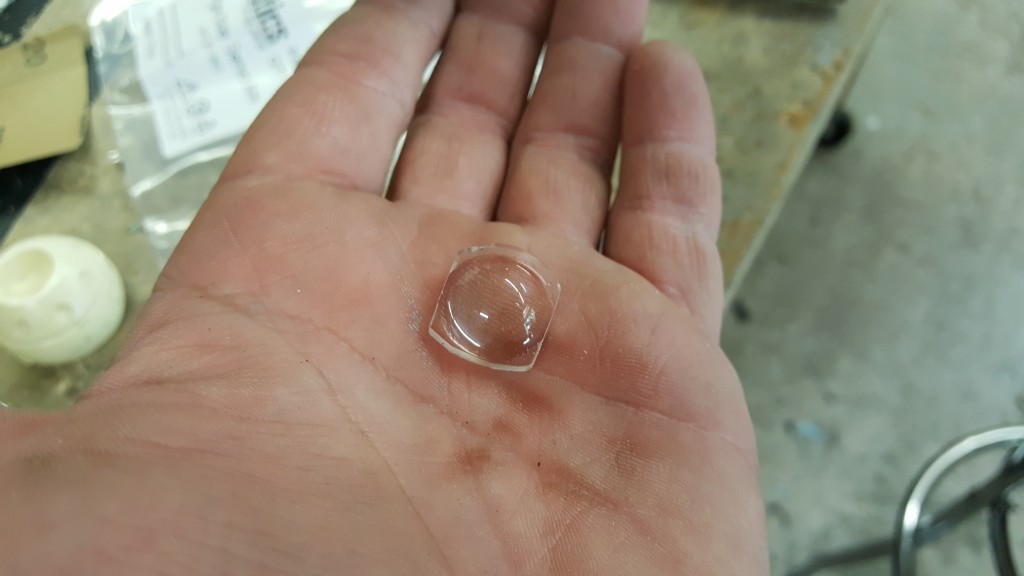
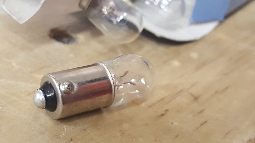
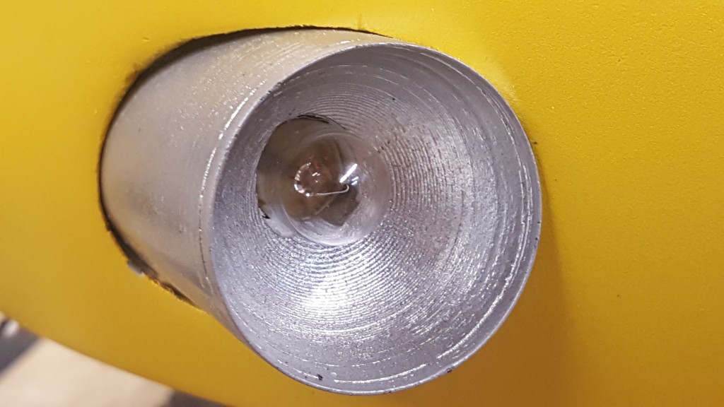
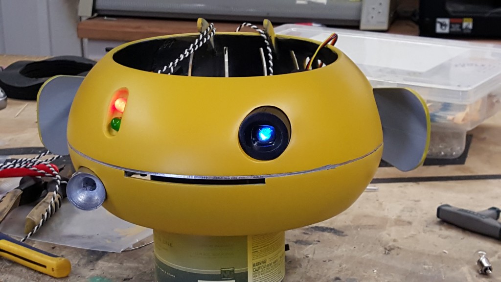
Get the Eye Lens part printed and sanded to fit into the hole on the body AFTER paint. I used a lens from a cheap LED flashlight ( AMAZON LINK ) and sanded it to fit inside the eye. I also added a blue LED that ends up being attached to my Arduino. The Red and Green LEDs on the other side of Weebo are 10mm frosted LEDs. These I discovered are hard to find. You can find them all day long in 5mm, and you can find red/green 10mm clear LEDs as well, but the frosted ones are tough. Luckily I did the hard work for you and found them in this kit. You get 2 sets, along with other LEDs. (AMAZON LINK) Those two should push through and sit nicely in Weebo. Now for the flashlight. Simply print this part, paint it up in silver and glue it into place. Again may take some sanding to get to fit. I used a pinball #44 12v light for this and they can be purchased here ( AMAZON LINK )
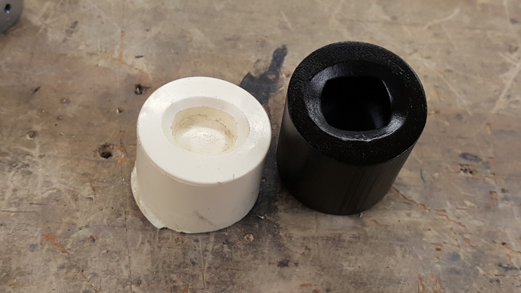

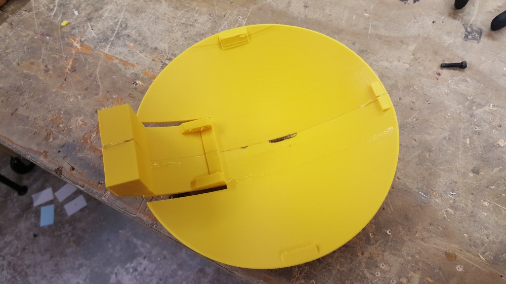
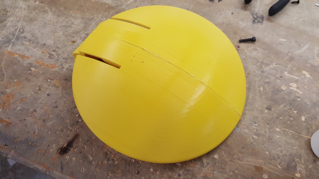
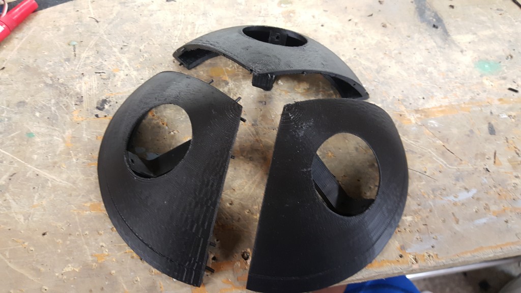
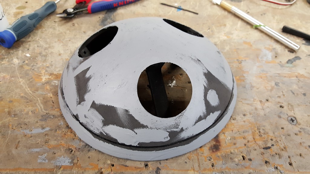
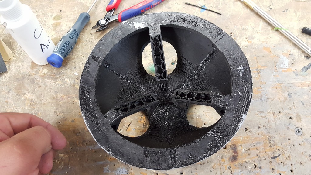
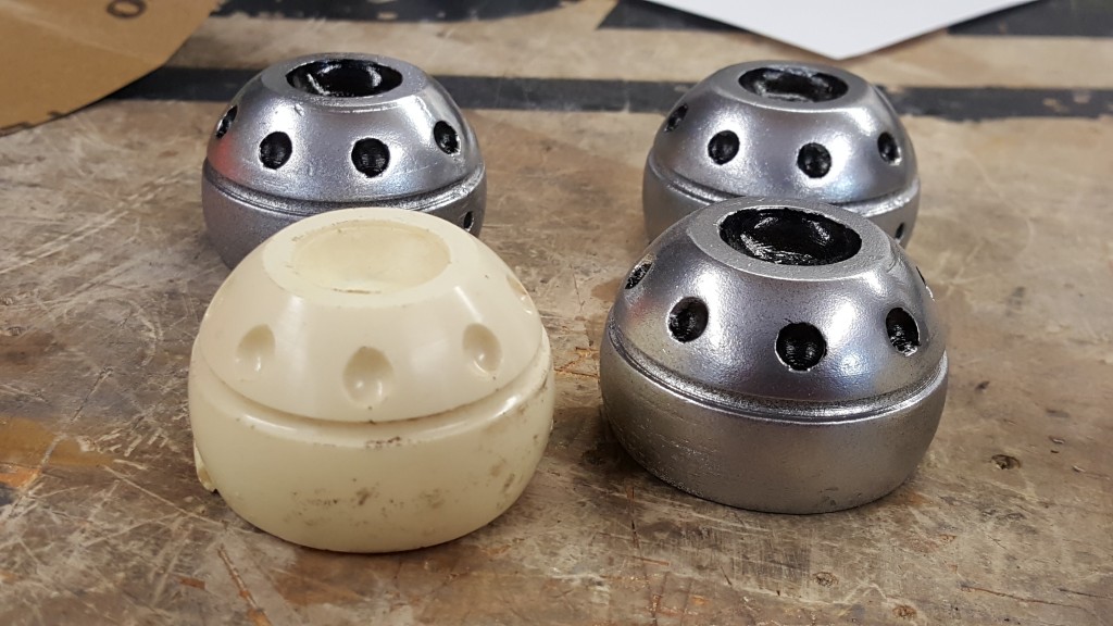
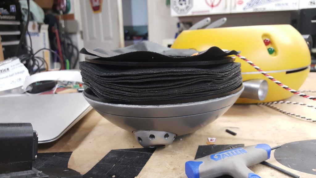
Lets get that lower jet setup made. Using the same technique as the main body, use filament and super glue to get the bottom turbine mount assembled. You will need 3 of these same parts to complete it. There is two versions of this in the zip file. One makes it easer to print without overhangs, but it will need to be cut and sanded after. This main portion will be painted a darker grey.
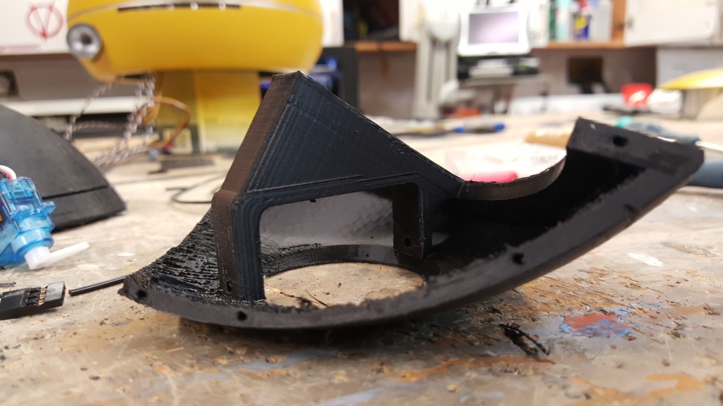
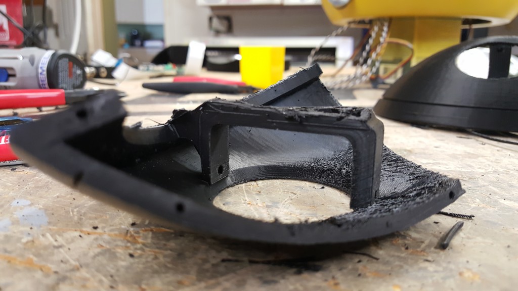
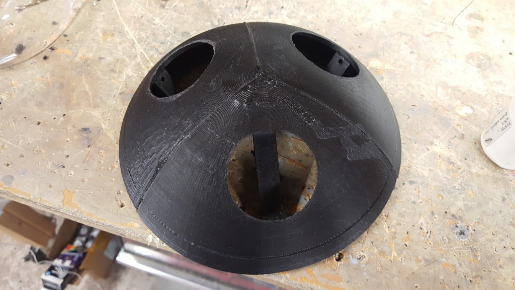
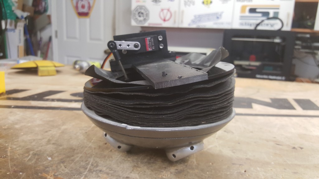
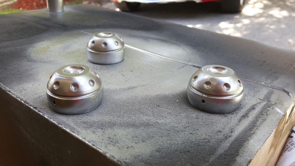
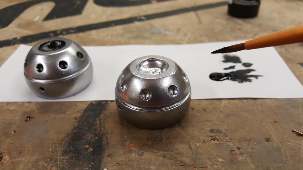
The small Jets will be mounted through the small holes into each bracket on the TurbineMount. Test fit this before you paint. I used small pins that I glued to hold them but still lets them swivel. After that, the jets were painted silver with black accents.
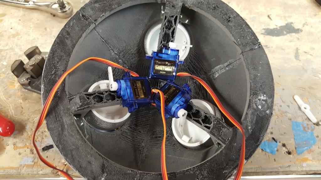
Small servos are then added and attached to the jets using small linkage. I used pro strength hot glue to keep the mini servos mounted. Video Below.
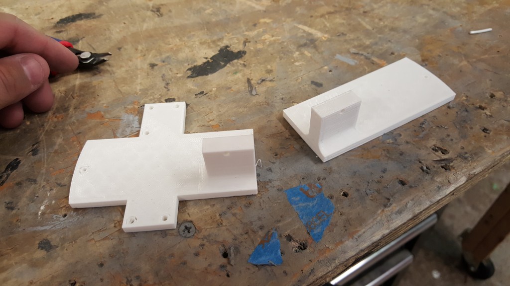
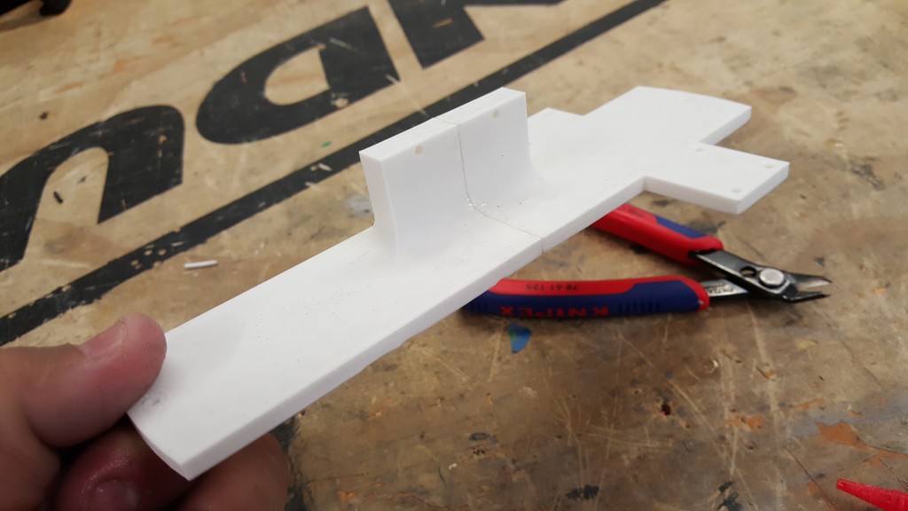
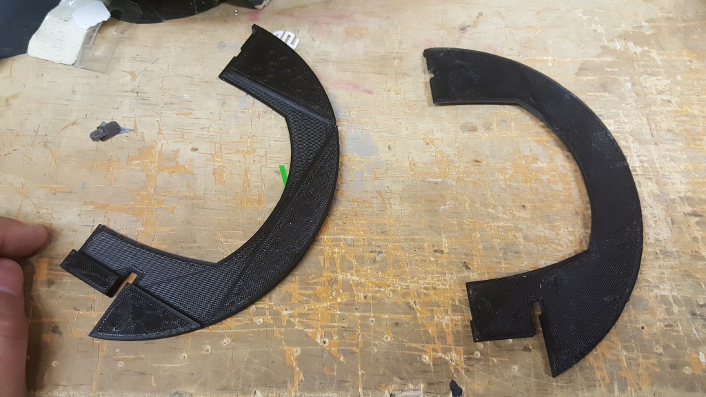
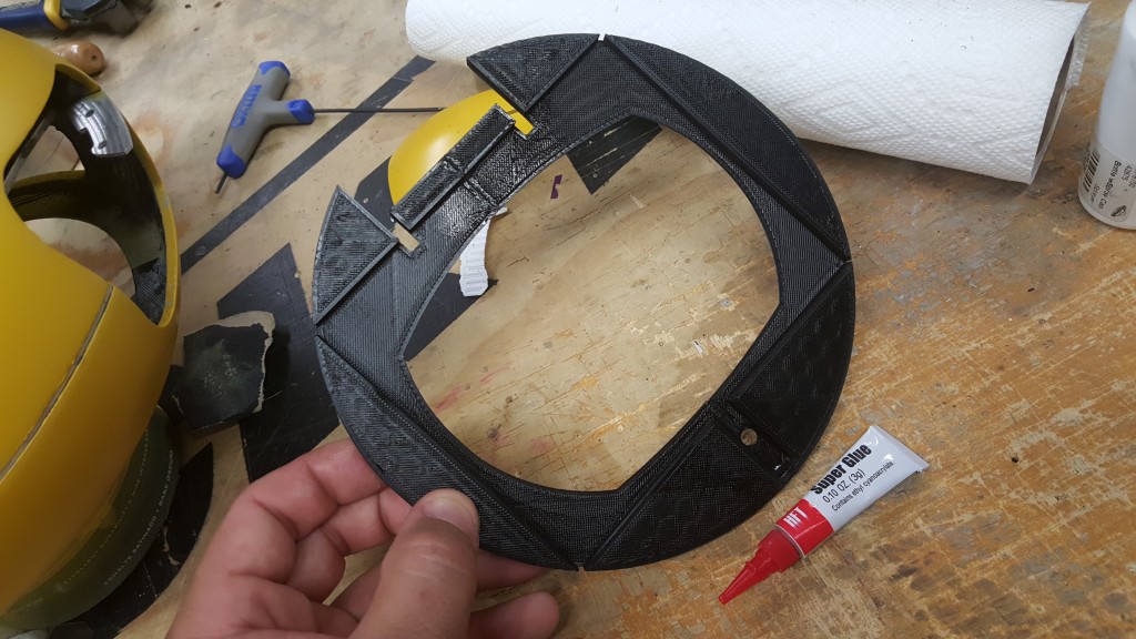
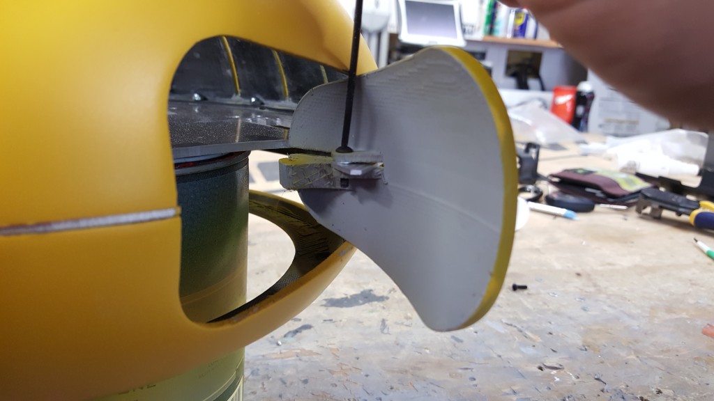
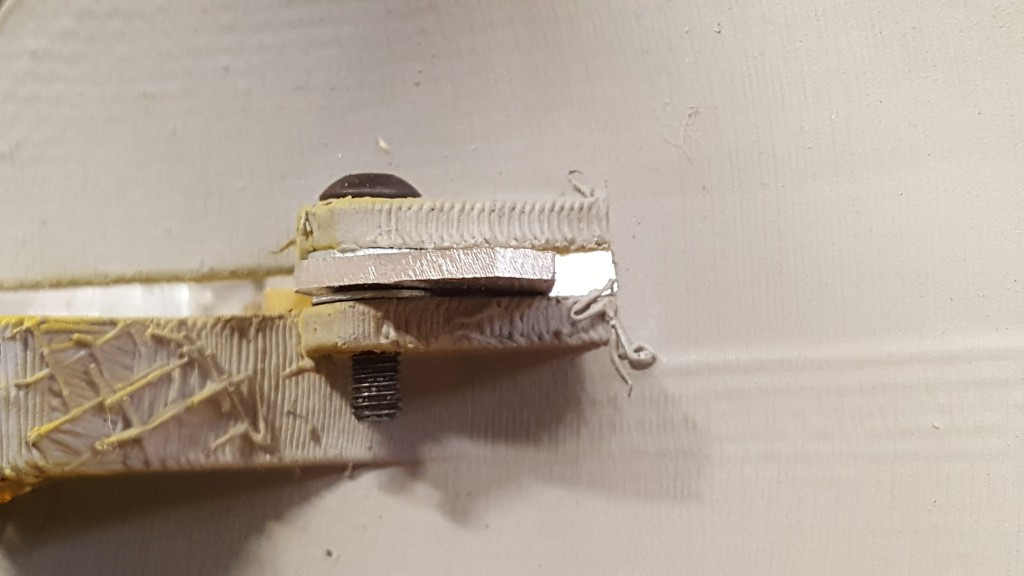
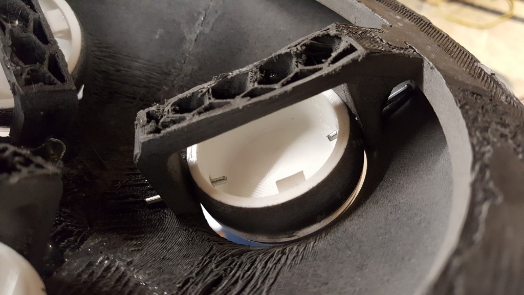
Using the DXF file named TurbineLowerMount you can print out a drawing of the mount you need to make that will be installed ontop of the Turbine Assembly. This is what the hinge and servo will mount to. I laser cut acrylic myself, but you can use any material you’d like. You could probably get away 3D printing it as well, but I did not include a STL in the file. After that, install the bellows from McMaster Part Number 5287K21 (McMaster Link) through the LowerMount and Turbine Assembly. Also add the two Brackets shown (HingeBracket and TurbineServoBracket)
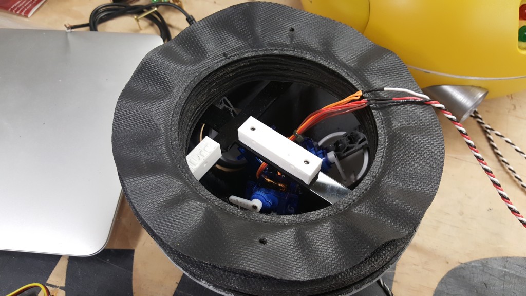
There is two parts named TurbineMount 1 and 2. Using more filament pins, assemble this and test fit it into the underside of Weebo. You will add the RightAngleServoMount here with a servo. Using the photos below, see how the servo is mounted with the linkage. Keep this assembly together and it will be installed later.