

Sorry for the blurry video.
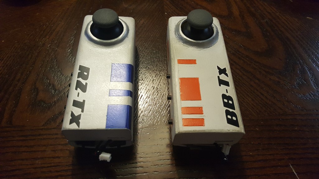
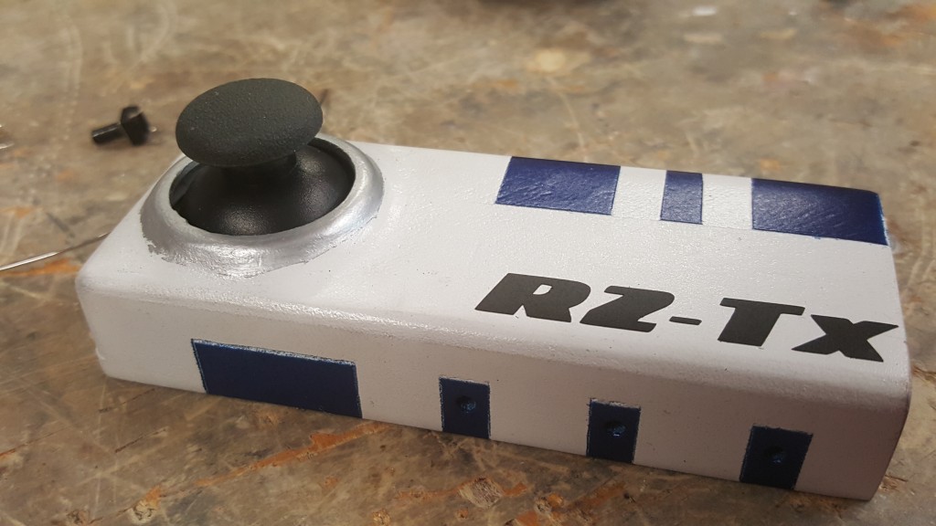
I have gotten quiet a bit of emails of people asking me how to wire the controller for my BB-8. I hope that this post can clear that up. I have just finished my R2-D2 droid and decided to use the same controller system as my BB-8, so as I was making it, I took pictures along the way and took a video at the end. I hope this can be a step by step guide for anyone. First up, the components…
3D Print STL files for Controller Here
Xbee x1 – https://www.adafruit.com/products/128
Xbee Adapter x1 – https://www.adafruit.com/products/126
Analog Stick Large x1 – https://www.adafruit.com/products/512
Analog Stick Small x2 – https://www.adafruit.com/products/444
Tac Switches – https://www.adafruit.com/products/1490
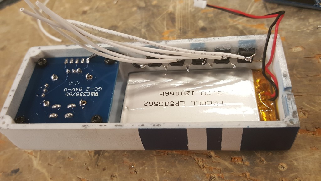
1200mah Lithium Battery – https://www.adafruit.com/products/258
Lithium Charger – https://www.adafruit.com/products/1904
Arduino Pro Mini 16mhz – https://www.adafruit.com/products/2378
Power SPDT Switch – https://www.adafruit.com/products/805
FTDI Programmer – https://www.adafruit.com/products/284
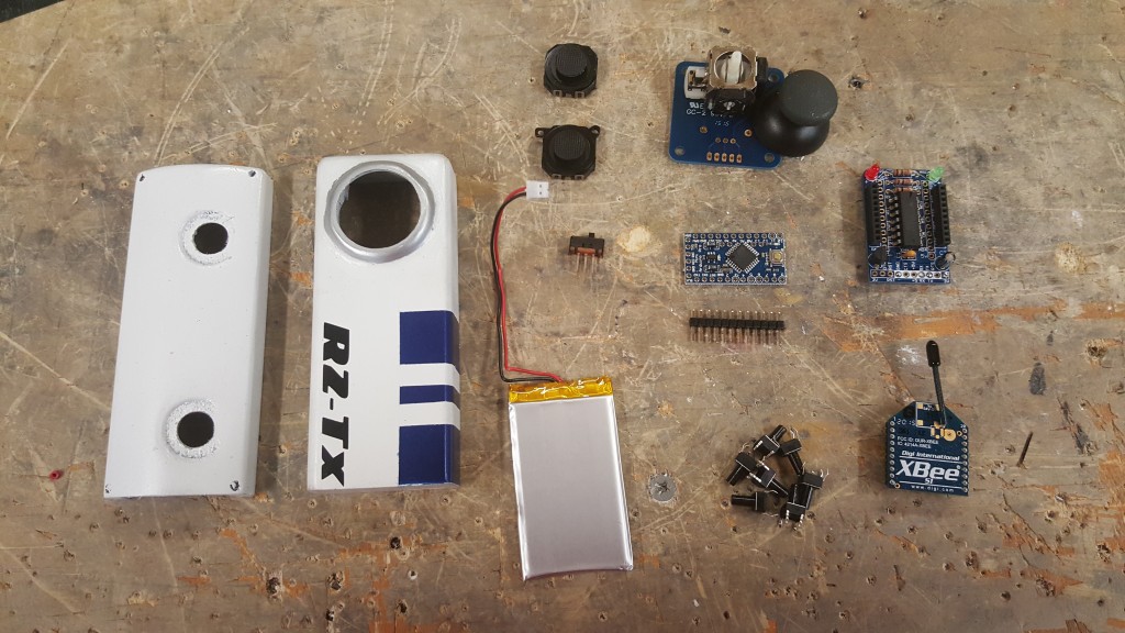
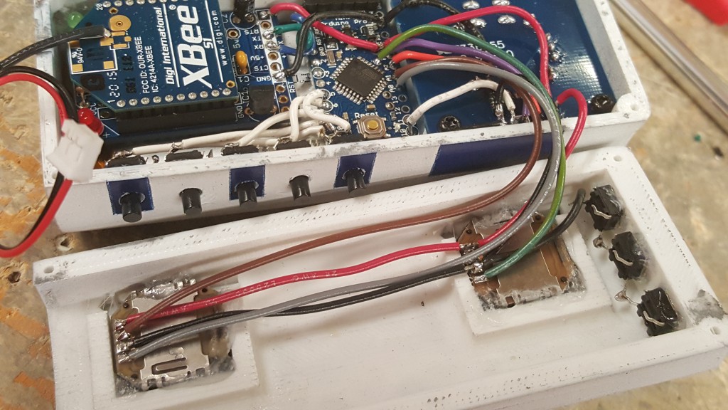
Check and make sure you have all of your parts. I have a few more tact switches in this R2 remote since I am adding more buttons for more audio functions. The controller STL files you printed have only 3 holes for pushbuttons, but you can easily drill more. More on that in the next few steps… For now, Lets get the Joystick soldered into the breakout board.
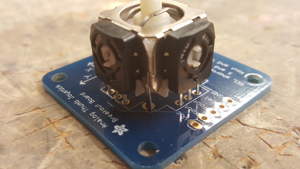
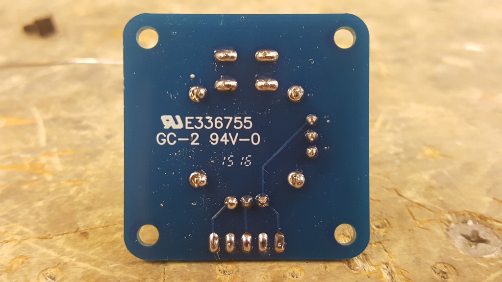
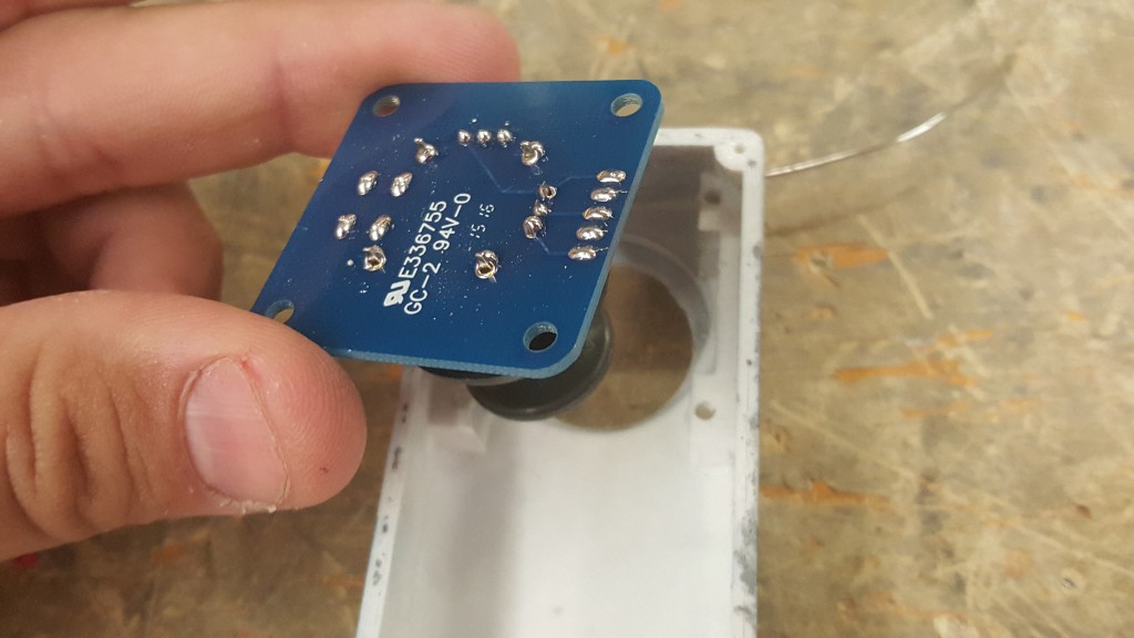
Pretty simple step. Just plug it on and solder it up, nothing to it. We will now install this into the top half of the casing. Sometimes support material is in the way when inserting the joystick, but you should be able to clear that out. The joystick will fit nice and snug. Secure it with 4 small screws.
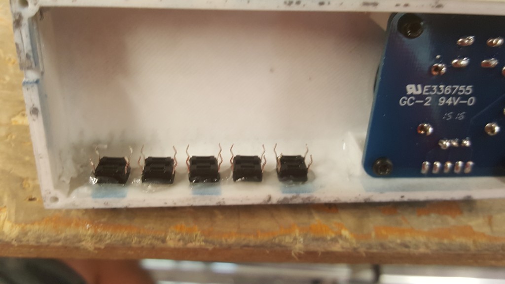
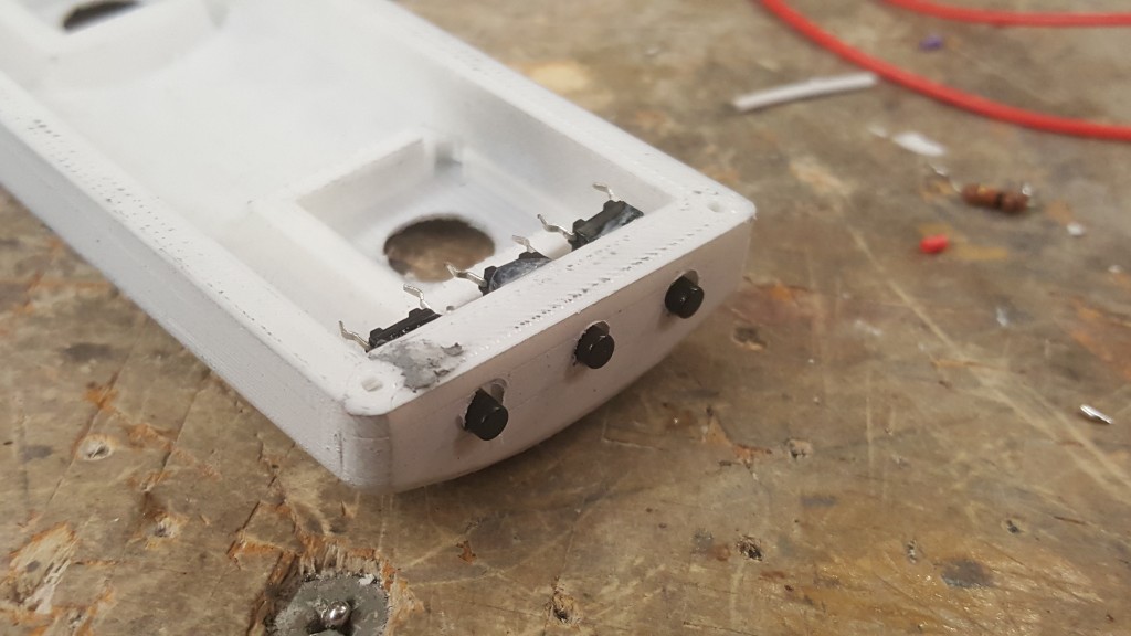
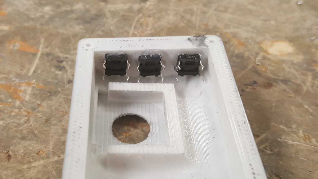
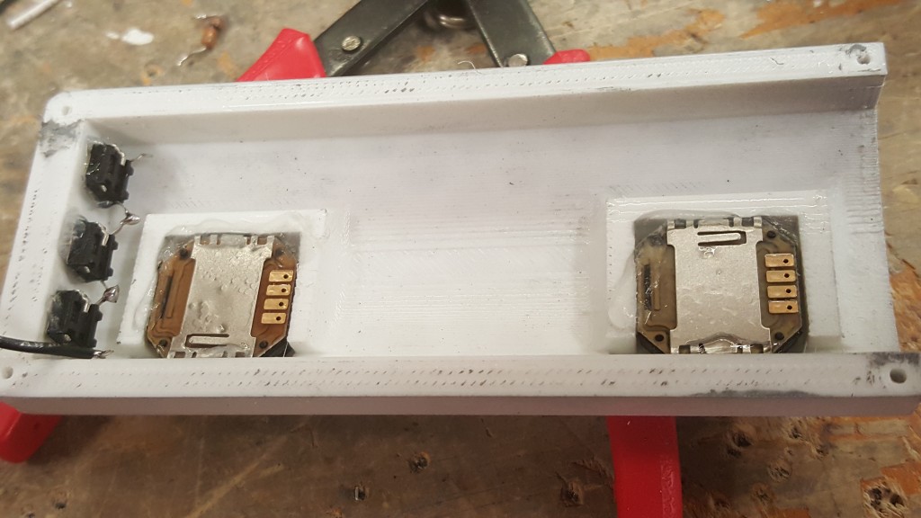
Now in this picture above you can see the 3 holes for pushbuttons that control the audio, I want to add a few more, so I am going to drill some new holes. You do not need to add more, but you can if you’d like. Once you insert the switches in, use a small amount of Super Glue GEL to secure them (be sure to use the gel so it doesn’t run into your switch and lock it up). Make sure they are in the same orientation as below.
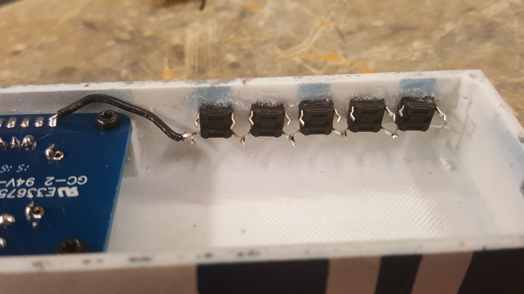
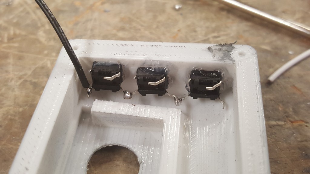
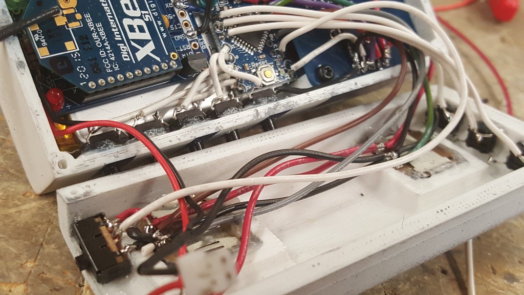
We are now going to solder the ground wire for all of these switches. They are going to use the internal pull-up resistors built into the Arduino, so no need for separate resistors. Simply bend the lower pins until they touch and solder them up. That will simplify connecting them to ground. Add a short black wire to the last button to solder to the last pin on the joystick (as seen below) This is a ground and will be wired to everything else later.
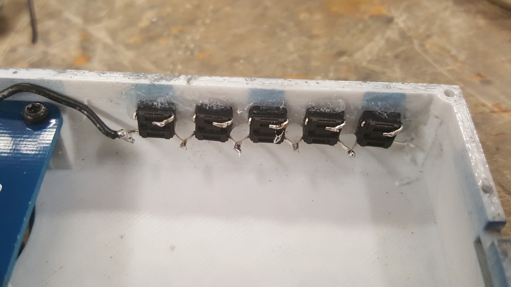
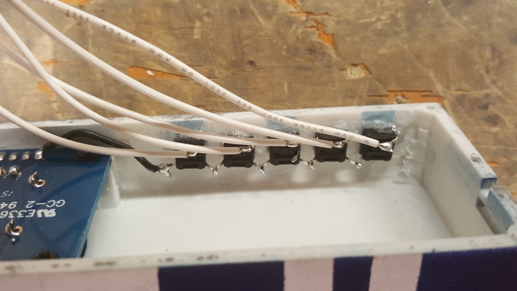
After this, we are going to clip a pin on each switch, this will just make it easier to not short anything out when we cram everything together. See the photos below on which pins to snip, then bend the other pin over (again to save room and eliminate shorts) After you do this, solder a wire to each button and set them to the side.
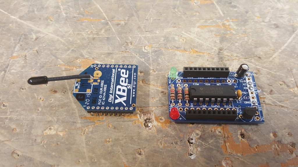
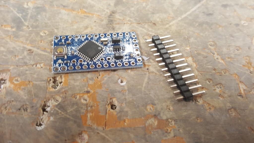
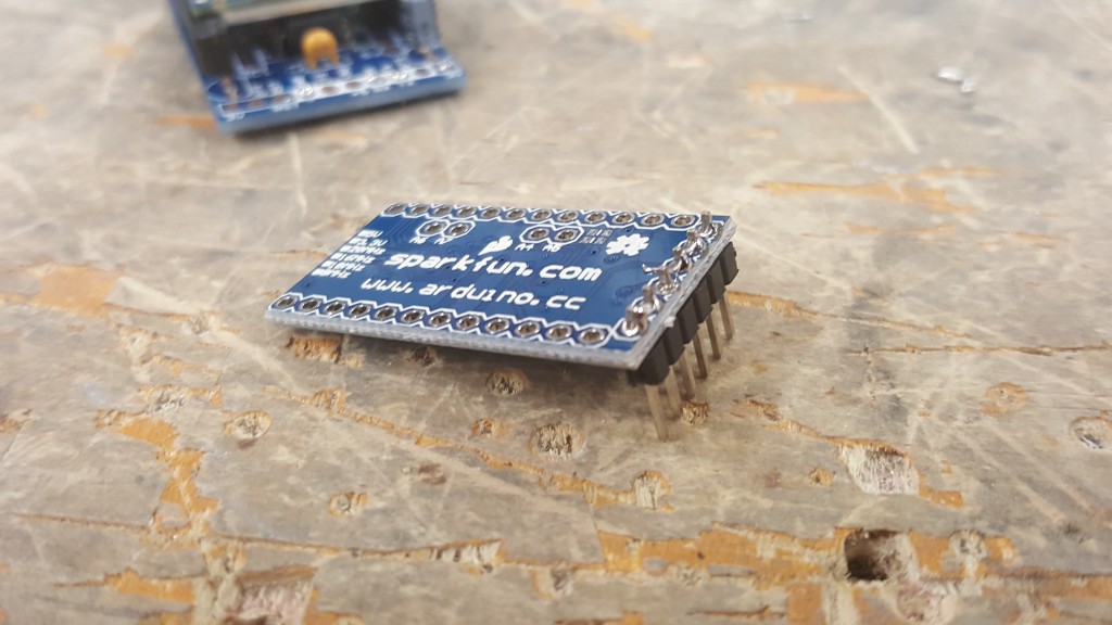
Solder a set of straight male headers to the Arduino’s programming side. This will make it easy to program your remote after you finish. If you haven’t assembled your XBEE adapter kit, please do that now. (Instructions are HERE For this build, program your XBEEs to how you would like them. I use stock configuration except I changed the buad rate to 38400 and changed my channels. After you program them, cut off the headers on the end. It makes more sense to buy an extra adapter to use for programming if you can. You can also use just the XBEE without the adapter in the remote if you’d like, but I installed mine.)
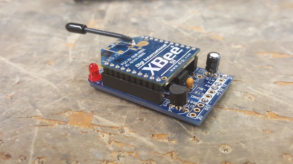
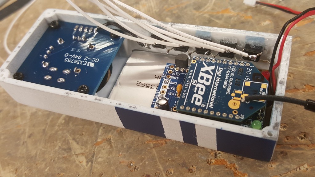
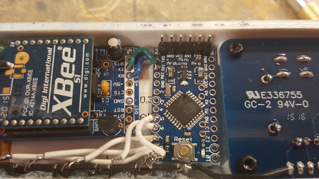
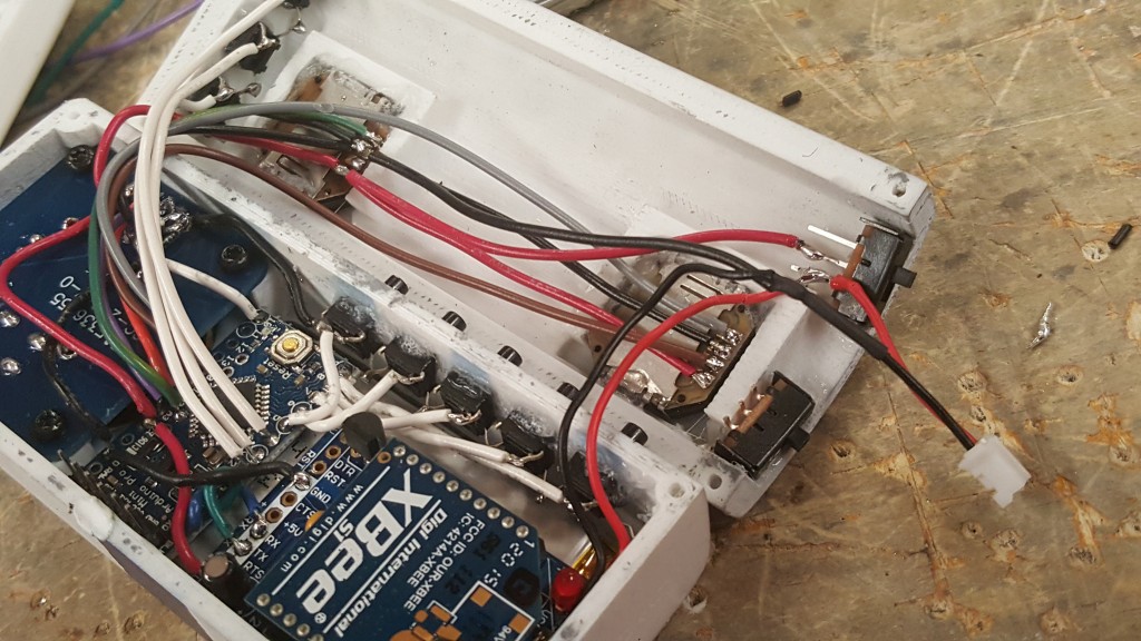
Now we are going to glue the battery down. I choose hot glue because if I want to release it, a small amount of rubbing alcohol will let it pop right up. On top of the battery I am gluing down the XBEE adapter and the Arduino. Please note the orientation. This helps with the wiring.
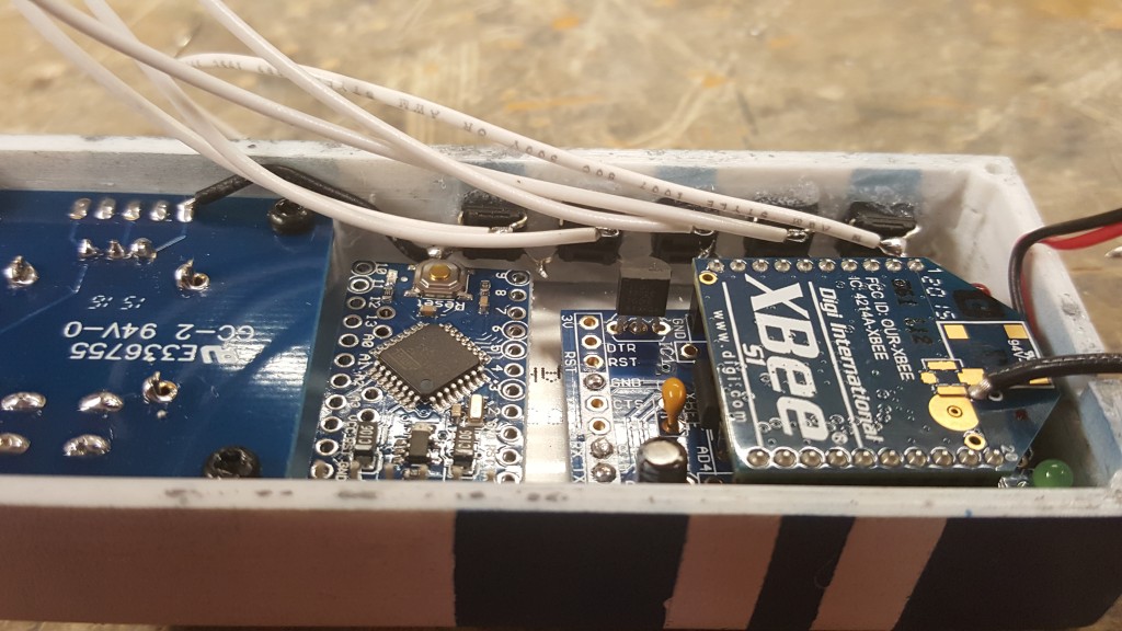
Now, lets solder those pesky wires attached to your push buttons, If using all 5 like I am, solder them to pins 5-9 on the Arduino. If using 3, just do it on pins 5-7. Get the wires as short as you can to save room. The key to this remote is to use as little space as possible.
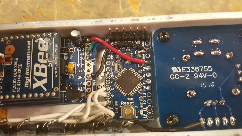
After that, lets get the XBEE wired up with serial and power. You will be sending out the date via the TX and RX lines between the Arduino and XBEE. Make sure you invert these, as in RX goes to TX and TX to RX as seen here.
Now for power. Come out of the 3v Pin on the XBEE into the VCC pin on the Arduino. Then your ground, GND to GND on the Arduino. Again I stress, short wires!
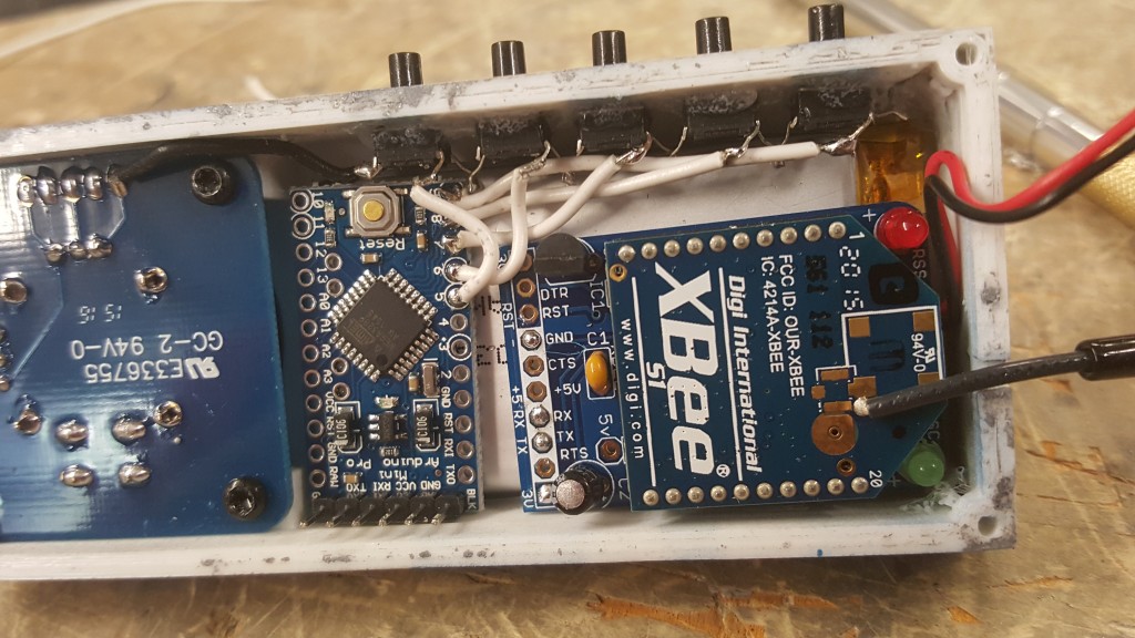
After you do that, your going to want to daisy chain these two lines into the joystick. Use the photo below to see the pins. That way its a big chain of power and ground and not each component getting their own feed from the battery. This is perfectly ok and works just fine. Notice the Ground pin is the same we used for the pushbuttons.
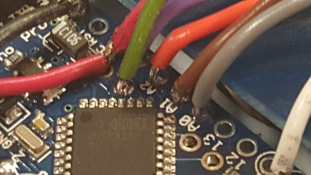
Now, lets wire up the X and Y pot pins from the Joystick to the Analog input pins on the Arduino. Using the photo below, wire up X and Y to Analog pins A2 and A3. The white wire will be soldered to the remaining pad on the joystick to digital pin 10 on the Arduino. This is the signal for the button inside the joystick when you click it down (Like zooming in with the pistol on Halo 1)
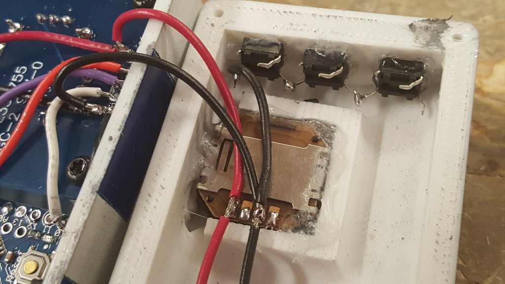
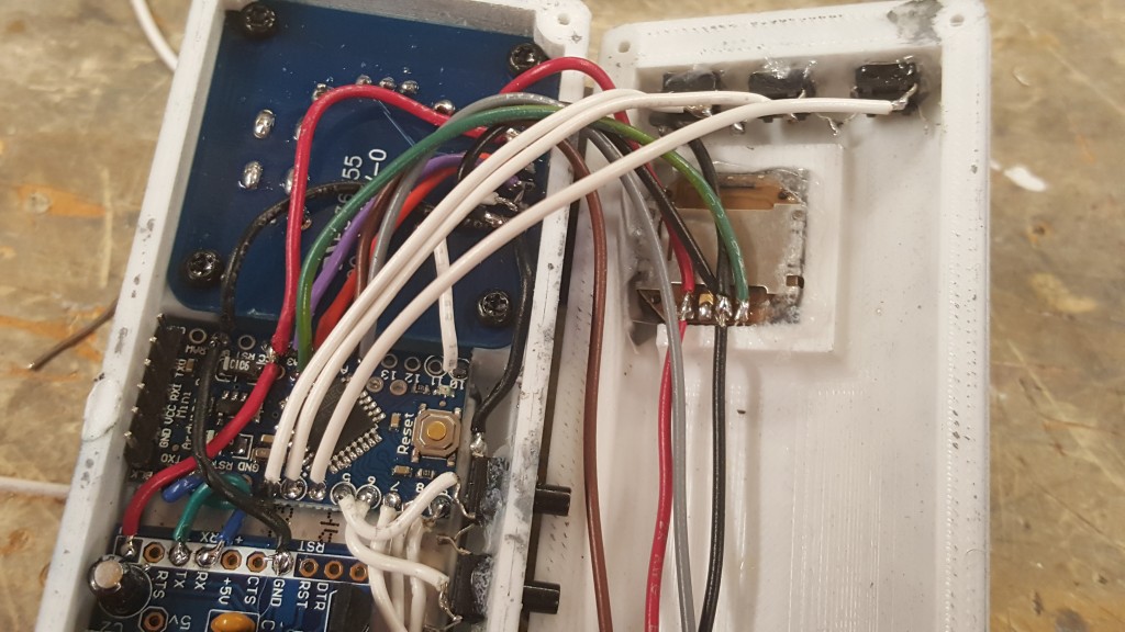
We are getting closer! Set the top half of the controller to the side and grab the back half. I added 3 more push buttons to the top of my controller. After using my BB controller for quiet some time, I realized that a few buttons up here would be comfortable and useful. Wire them up just like you did before.
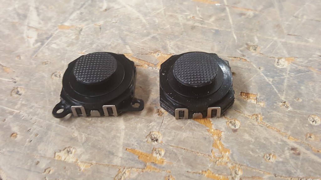
We are going to glue in the Small PSP thumb joysticks into it. Before you put them in, you will need to snip off the two tabs on each stick. Shown here…
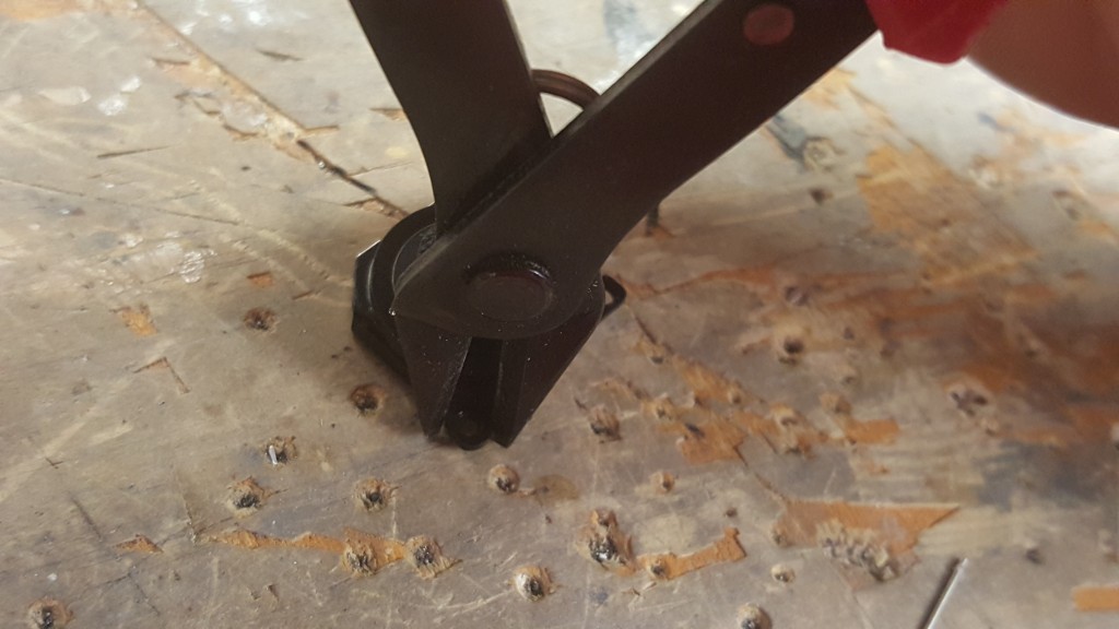
It may require some filing to get the holes big enough to fit the thumbstick in, but it will work. Push the sticks in with the pads facing down (see below) then after they are in and have some play to them (dont want them to tight as they will stick when using them. You want them to snap back easy.) Again using Super Glue GEL glue them in place.
Now lets get power and ground to the thumb sticks. We want to run the least amount of wires between the two halves on the shell, So we will again daisy chain coming off the main analog stick on the top half of the case. Watch the pins you solder to!
Now go ahead and give the top buttons ground by soldering it to the pad on the top thumb stick. We don’t want to run that wire between the two halves remember, so this way it saves space.
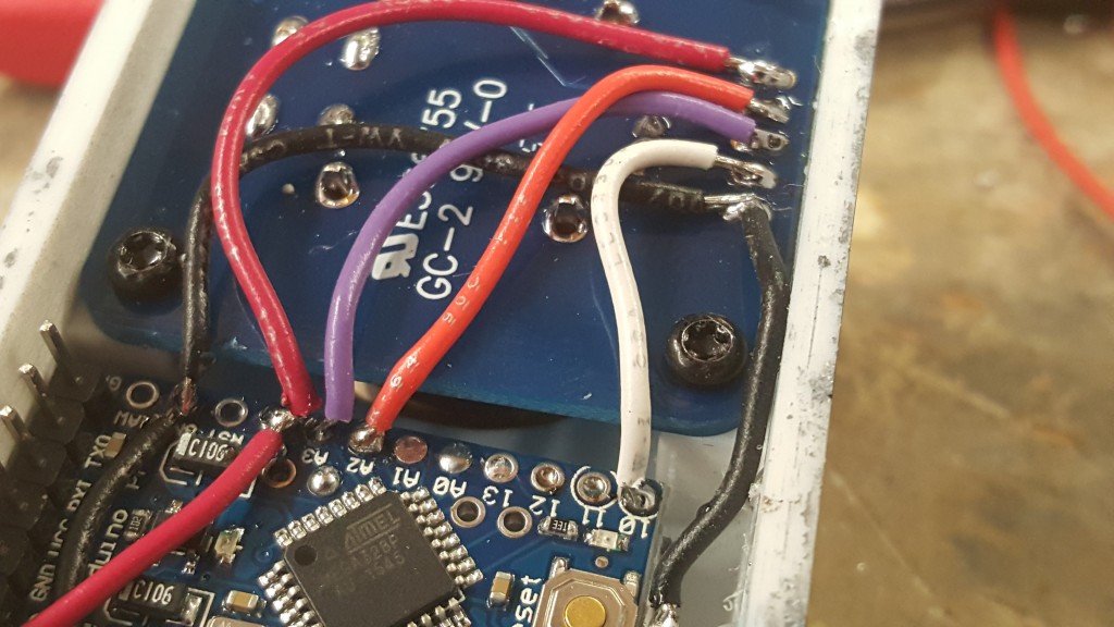
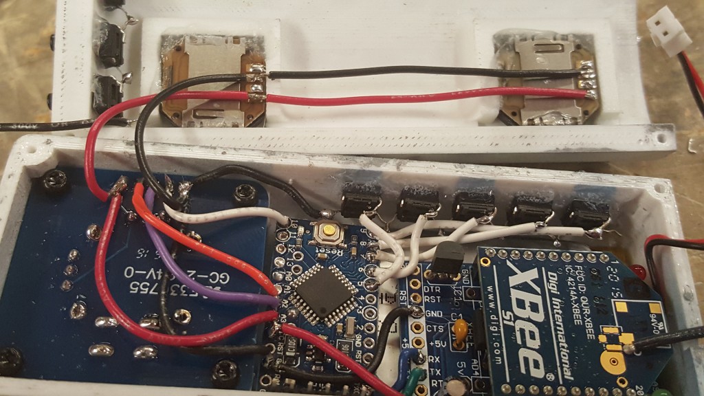
Now for the pot pins on these thumb sticks. I am using the X and Y of the bottom stick and only the X from the top. In my R2 config the top stick controls the dome pan, and the bottom controls the Holo projectors X and Y. Its up to you how you do this. But in my case I wires to Analog A0, A1 and A5. A5 is not marked on the Arduino Mini, but you can see it in the second photo which one it is. Its where the green/yellow wire is soldered into.
Now lets get those top buttons wired in. They go to Digital pins 2-4 in my setup.
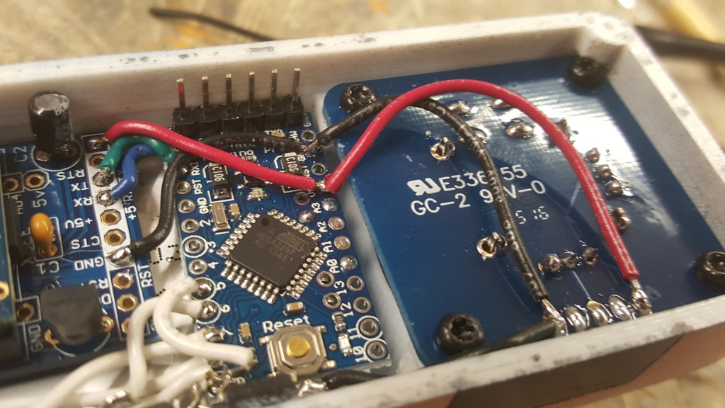
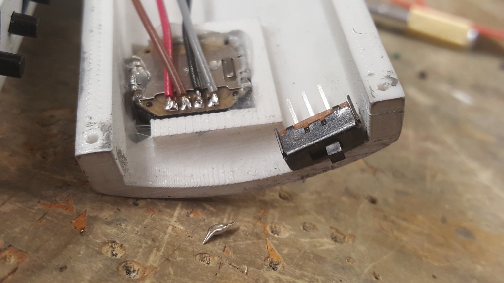
This should all be coming together now! Lets get the battery wired up! I glue down the power switch to the bottom half of the case. Makes it easy to get to when turning on and off your controller. Then wire up the 3v line along with ground from the battery as shown in the second photo. Only the 3v line goes through the switch. Leave the connector on the battery like shown so you can charge it up when not using it. You can charge it while using it as well if wired like in my photo.
You can see in this photo above I have a second switch. I wired it up to ground and Digital pin 12. This is a option I put on my unit to allow a “auto” mode that will make R2 or BB-8 move their dome around and talk on their own randomly. This is not a necessary step.
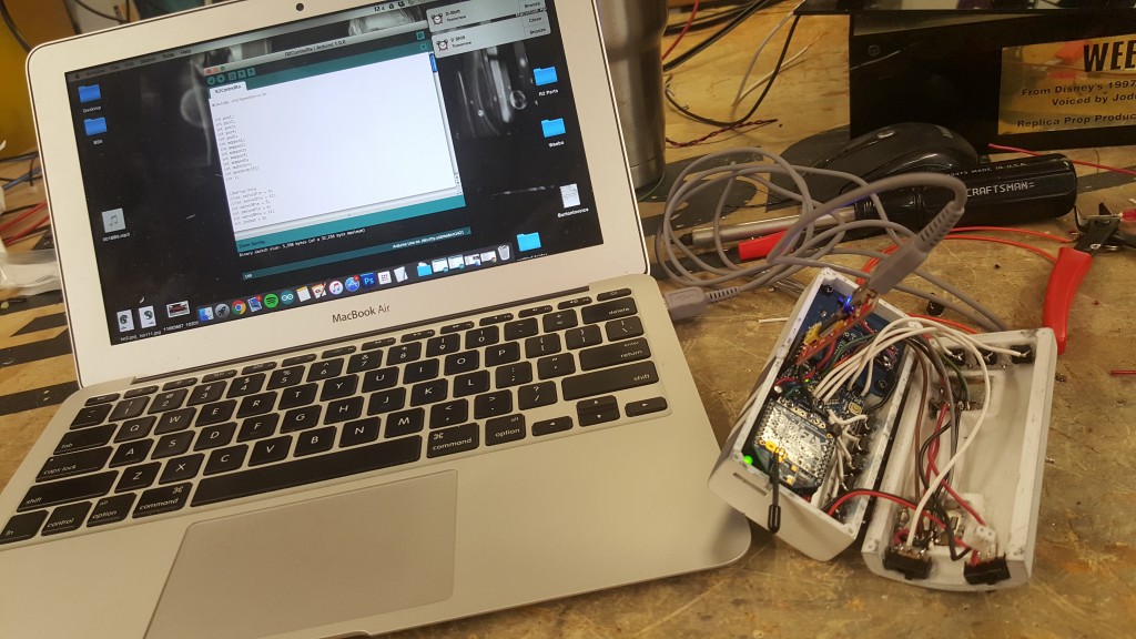
Alrighty that is it! Hook up your FTDI and program in the code. I have attached my new version of the code below for you to use if you’d like. Each setup will require your own way of coding. I am in no way saying this code will work for you, but with some Arduino experience you will be up and running quickly! Good Luck!
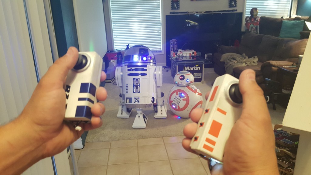
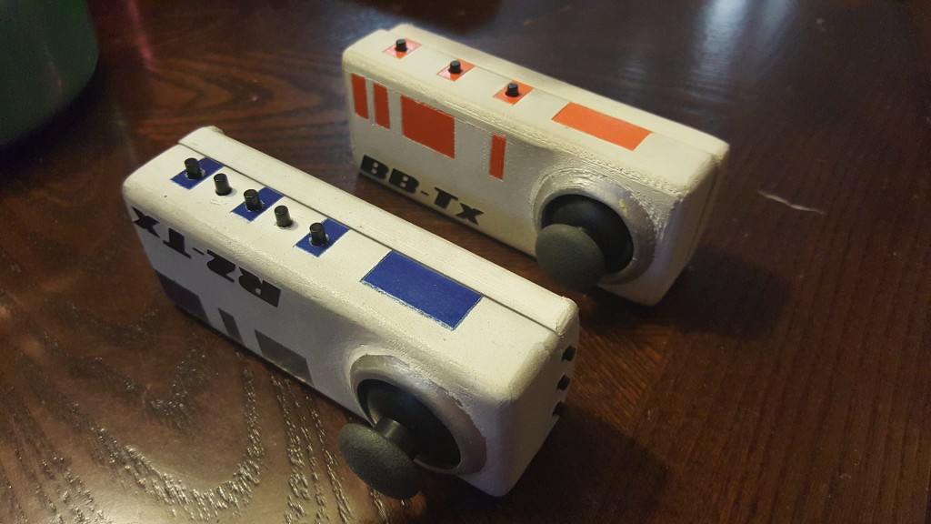
I could even control both at the same time if I wanted to!
Here are the new Arduino Sketches for download. – R2-TxControl
Sorry for the blurry video.