


DOWNLOAD FILES HERE
DXF Files – Designed to be cut out of 1/4″ Aluminum
STL Files – Designed 3D Printed at 100% infill
Parts Needed
http://www.calplastics.com/
20″ Hemisphere – Part Number – 02-PD500CP-0003
McMasterCarr
Shaft Mounts Qt 2 – http://www.mcmaster.com/mv1454704298/#catalog/1865K2
3/8″ Shaft (12″) – http://www.mcmaster.com/mv1454704298/#catalog/6061K32
3/8″ Shaft (3″) – http://www.mcmaster.com/mv1454704298/#catalog/6061K418
3/8″ Bearings Qt. 4 – http://www.mcmaster.com/mv1454704298/#catalog/60355K504
1/4″ Shaft 12″ x1 – http://www.mcmaster.com/mv1454704298/#catalog/5947K11
Timing Pully – x4 – http://www.mcmaster.com/mv1454704298/#catalog/6495K23
Timing Belt x2 – http://www.mcmaster.com/mv1454704298/#catalog/6484K702
Servo City
Spin Motor x1 – https://www.servocity.com/html/98_rpm_econ_gearmotor__638350_.html#.Vrpaw_krKt8
Continous Servo x1 – https://www.servocity.com/html/hsr-2645cr_servo__continuous_r.html#.VrpcQfkrKt8
Servo Blocks x1 – https://www.servocity.com/html/standard_hitec_servoblocks.html#.VrpcbPkrKt8
RobotZone Servo System 90degree 7:1 x2 – https://www.servocity.com/html/spg7950a_standard_rotation.html
Clamping Hub Youll Need x2 (545588) x2 (545616) – https://www.servocity.com/html/0_770__clamping_hubs.html#.VrpfDvkrKt8
Drive Motors x2 – https://www.servocity.com/html/23_rpm_hd_precision_planetary_.html#.Vrpgp_krKt8
Motor Mount E x2 – https://www.servocity.com/html/aluminum_motor_mount_e__555188.html#.Vrpg1_krKt8
1.5″ CHannel x2 – https://www.servocity.com/html/1_50__aluminum_channel__585440.html#.VrphJPkrKt8
Bearing Channel PIllow mount x2 – https://www.servocity.com/html/1_4__ball_bearing_quad_pillow_.html#.VrphlPkrKt9
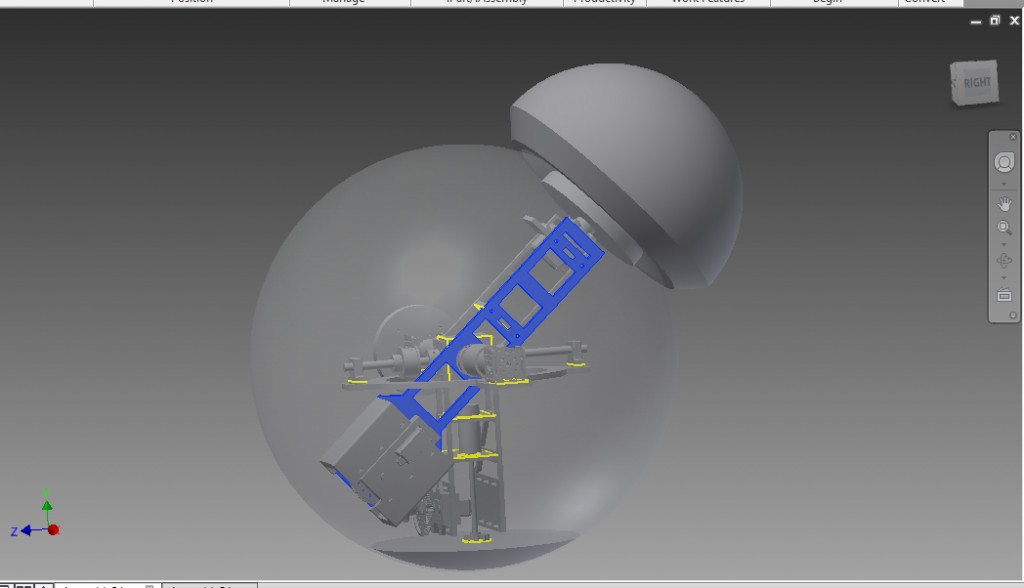
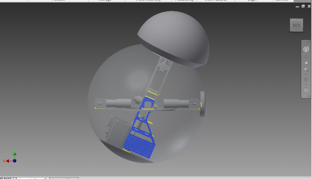
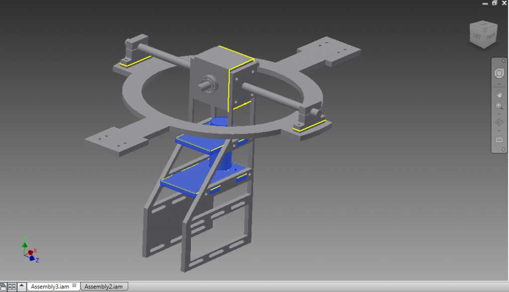
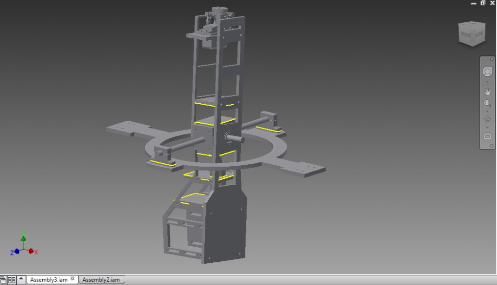
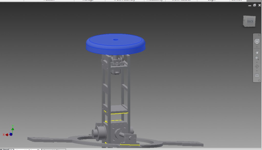
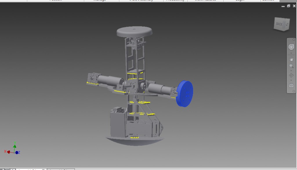
Well here is what the drive system looks like when its finished..
Now lets take the parts and get to work! Please note, that I am only giving away my files and advice here. I am not going to have the time to answer all questions on how to build him. It takes a good background in engineering, RC and CNC/3D printing to do this. I always say give something a shot and learn the skill while building if you can, but this is not considered a “beginner” project. It is for the experienced builder.
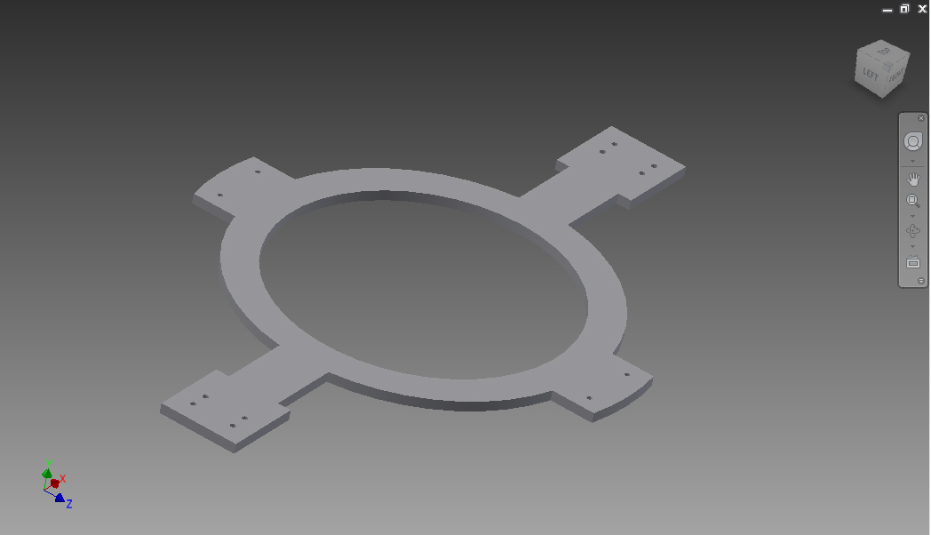
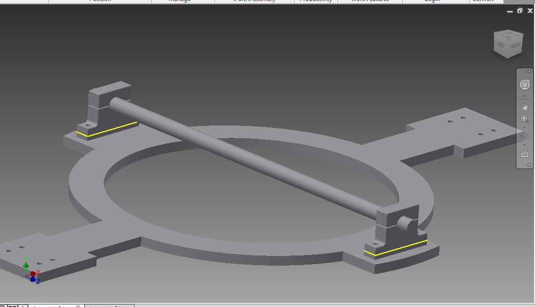
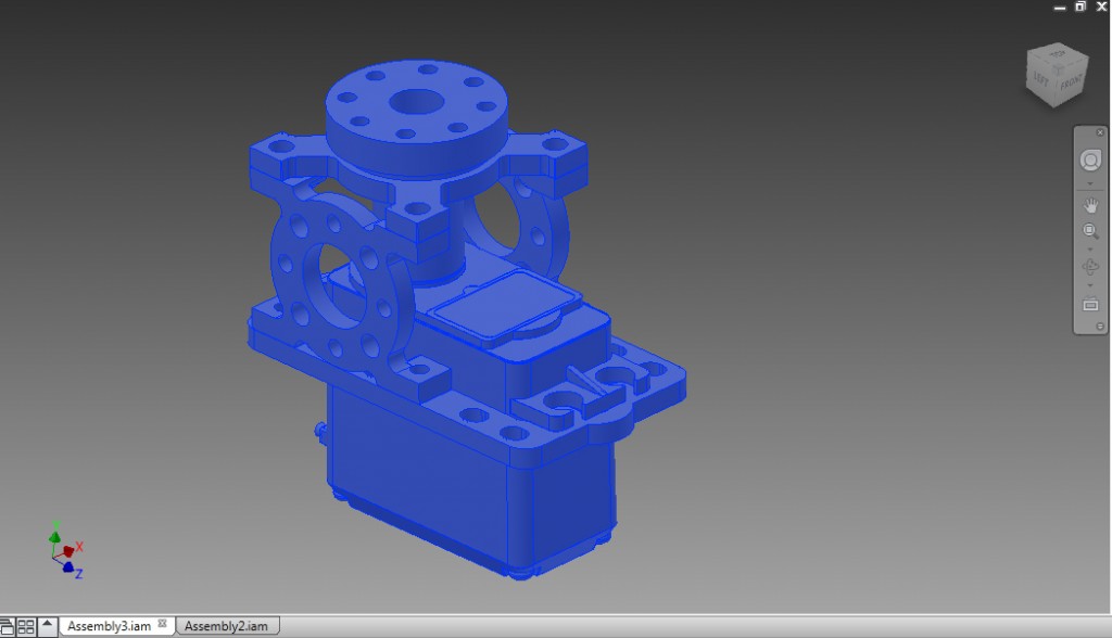
Go ahead and take the part that is our main carriage. This is what the whole system is help by and hangs on.
We are going to attache the 3/8″ Shaft (http://www.mcmaster.com/mv1454704298/#catalog/6061K32) to this carriage using the shaft mounts (http://www.mcmaster.com/mv1454704298/#catalog/1865K2) to the front and back of the carriage. Before you screw them down tight, check out the next few steps for what else needs to be attached, like the main pendulum joint.
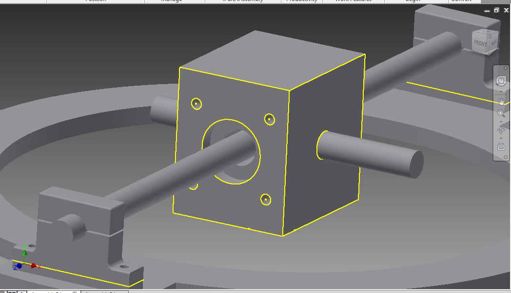
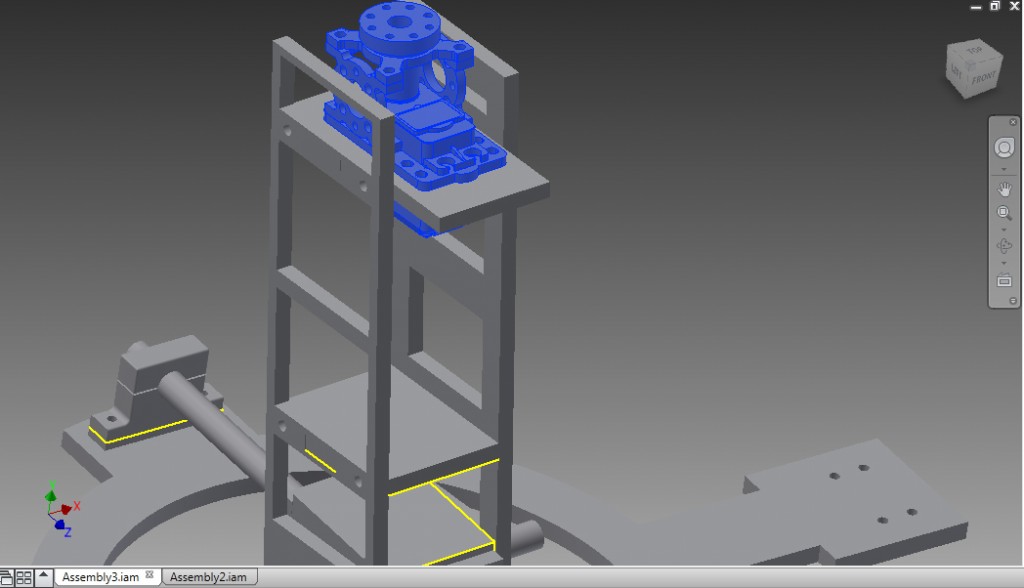
Go ahead and mount the pendulum Joint along with the bearings (http://www.mcmaster.com/mv1454704298/#catalog/60355K504). Also Using the smaller 3″ 3/8 Shafts (http://www.mcmaster.com/mv1454704298/#catalog/6061K418), place those on the sides. I used a setscrew to keep them in place, but whatever you prefer to use. They need to be mounted in there enough to no let them spin at all. They will be taking stress when trying to tilt the dome, so make sure they are secure.
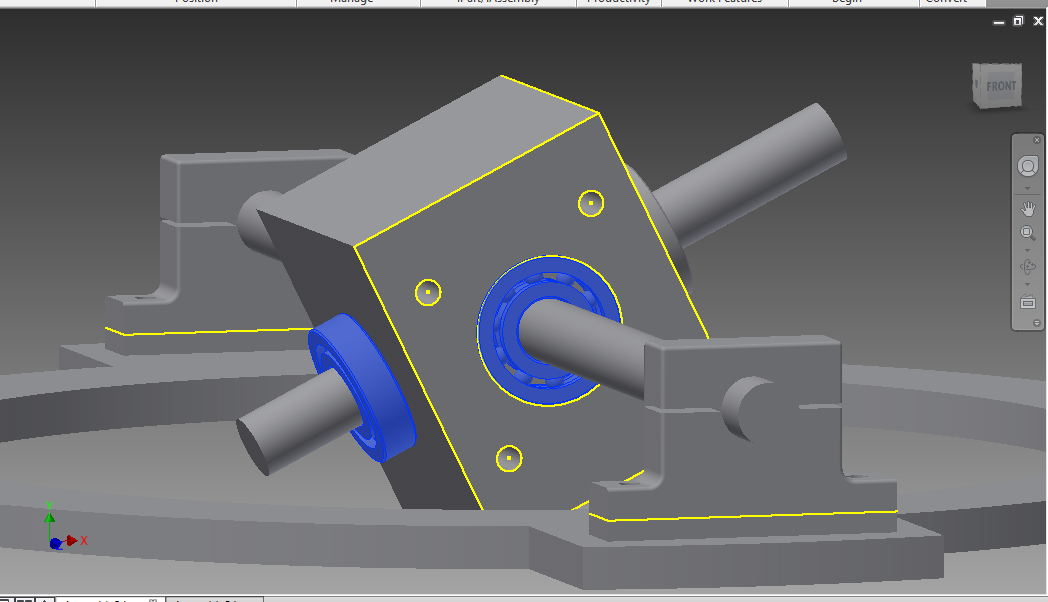
Now that you have the joint installed, we are going to start installing the pendulum system. Note that these are mounted to the joint and swings along the 12″ 3/8 shaft. There should be a small gap between the shaft on the hole it runs through. That is normal. We really do not want the pendulum to touch the shaft.
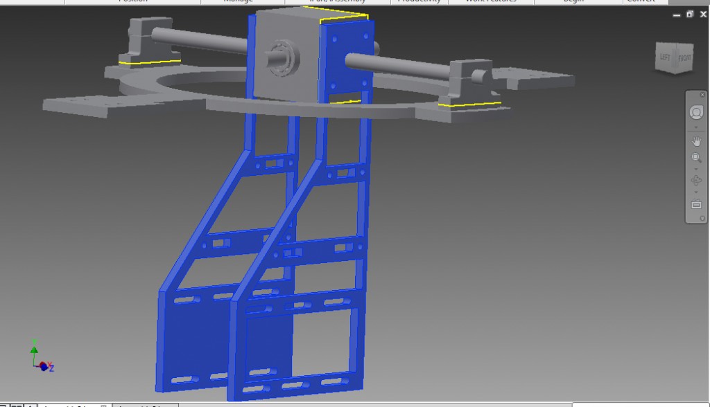
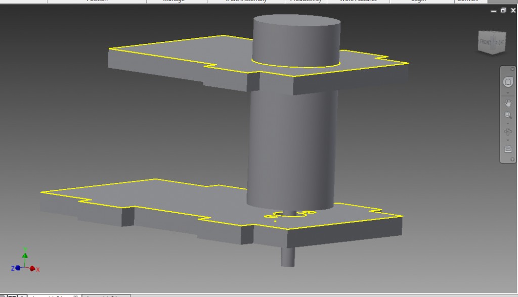
We want the pendulum system to have supports to make it sturdy. That is where to pendulum brace parts come in. Before we mount them we want to attach the spin motor (https://www.servocity.com/html/98_rpm_econ_gearmotor__638350_.html#.Vrpaw_krKt8) for the bottom counter weight. Now, again this is not perfected and it is the motor I am using now. I may be changing to a different system later as its not good for the motor to have that much weight pulling on it. Once you have the motor mounted, mount the brace parts into the pendulum. You may need to unscrew one side to get them in. You will want to tap and drill them into place as well. In fact when I cut out my parts, I did not use the tabs. That is up to you whether or not you will use them.
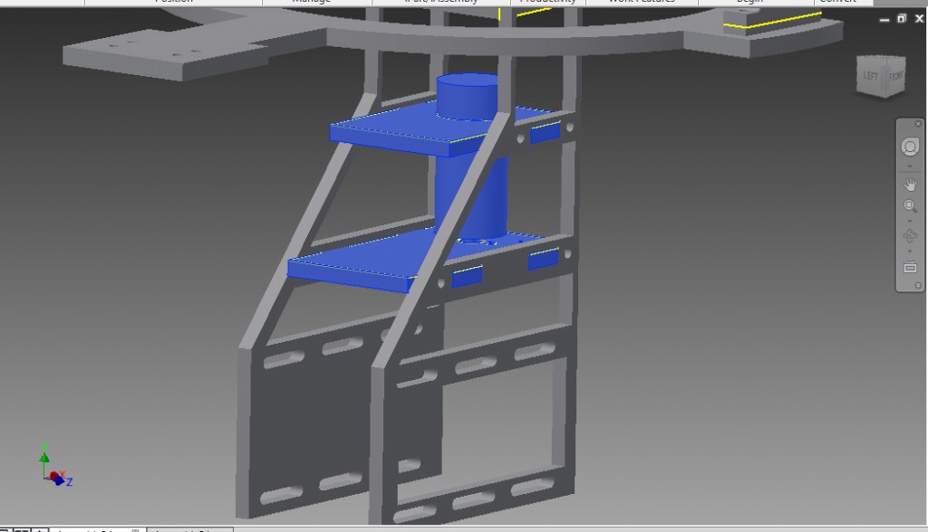
That motor will end up attaching to a counterweight at the bottom. The idea is when you spin the motor, the counterweight will spin one direction, which will cause the whole sphere to spin the other way. Well at least it tries. Now lets mount the dome arm system to the other side of the Pendulum Joint. We are going to mount these using those bearings you put onto the 3″ x 3/8″ shaft.

This arm also uses brace parts to keep it together. Go ahead and mount those two parts like we did the pendulum braces. Again, tapping screws to hold into place.
A Continuous servo motor is going to sit on the top of that arm. This will give the dome/head the ability to spin. Using the servo motor (https://www.servocity.com/html/hsr-2645cr_servo__continuous_r.html#.VrpcQfkrKt8) and the ServoCity Servo Block Kit (https://www.servocity.com/html/standard_hitec_servoblocks.html#.VrpcbPkrKt8) Mount that to the top Brace.
Now we can spin the dome and tilt it down the sphere. We are getting there!
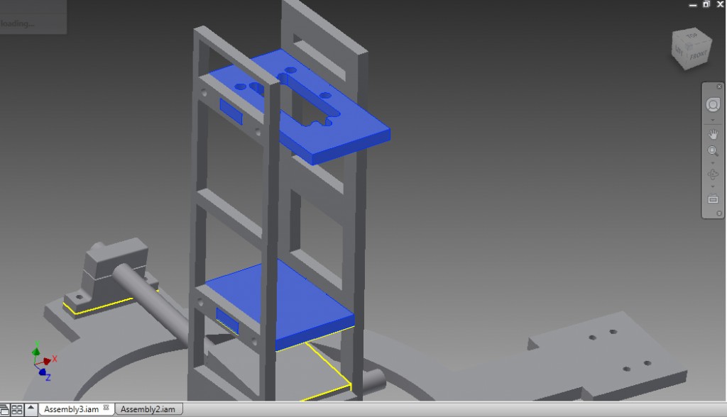
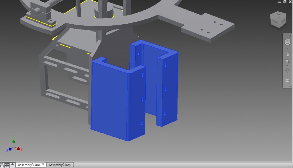
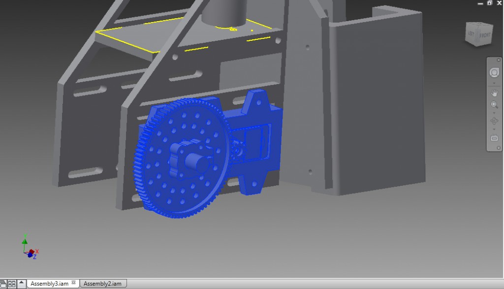
Using the Part in the STL file download, install the GearBox Brackets to the lower part of the dome arm. This is what are large servos are going to mount to. If you can get these made in aluminum, great, Mine were 3D printed in ABS at 100% fill and have been working great!
Go ahead and mount the Timing Pulleys (http://www.mcmaster.com/mv1454704298/#catalog/6495K23) and the shaft Clamps included in the STL files. You will have to unscrew the 12″ shaft to get some installed. Get them all tightened down real well. Note that you will not need a clamp on the arm side that has the pulley installed. It works as a clamp.
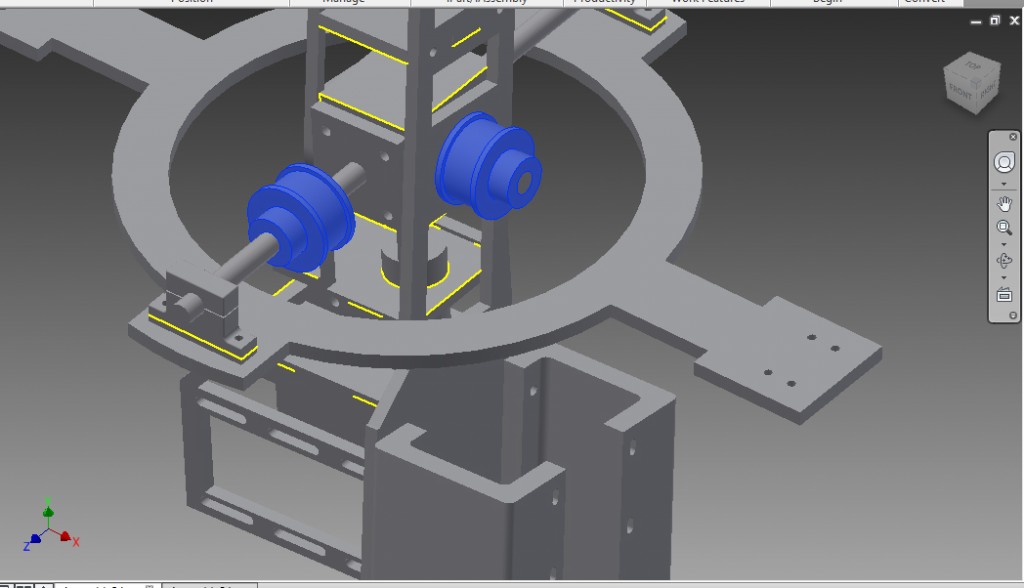
Now we are going to mount the brute force behind this whole operation. The Large ServoCity RobotZone Servo Systems (https://www.servocity.com/html/spg7950a_standard_rotation.html). Now, as you mount these along with their pulleys, you will want to add the timing belts (http://www.mcmaster.com/mv1454704298/#catalog/6484K702) at the same time and make sure the belts are very tight when installing. It takes some force.
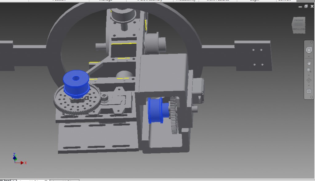
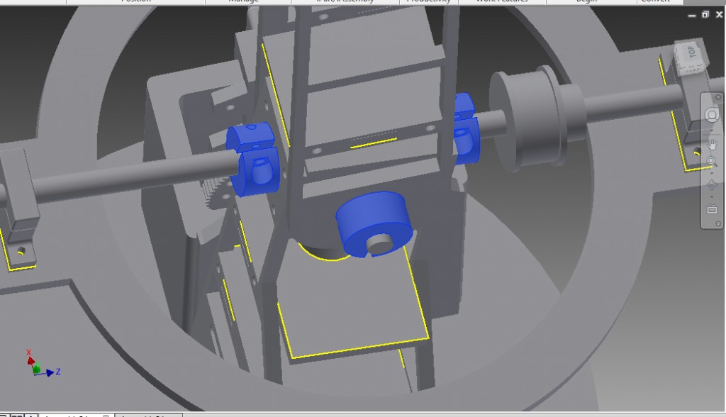
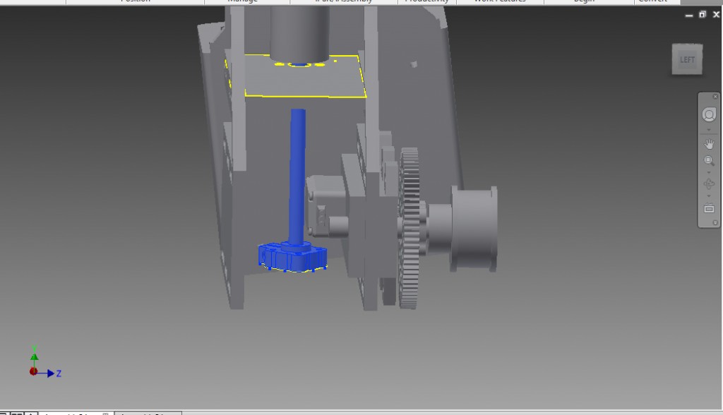
Now lets mount the counterweight you made and the shaft to the spin motor. We mount it using a ServoCity 1/4″ clamping hub (545588) and 1/4″ Shaft (http://www.mcmaster.com/mv1454704298/#catalog/5947K11). The length of the shaft will determin how you mounted everything. You want it as high as possible without interfering with the sphere or dome arm. You can also go ahead and mount the Magnet mount (From the BB-8 Builders Club) to the servo at the top of the dome arm.
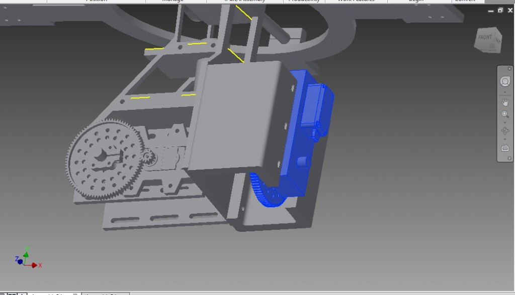
Now for the Drive motors. In the pic below It shows them mounted using bearings to hold the weight. This helps, yes, But in mine I just mounted the motors directly to the Sphere Mounts (In STL File) using a 6mm hub clamp from ServoCity (545616) Y
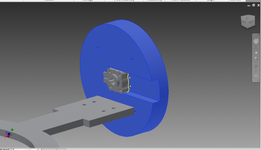
You can use the servo city channel to mount the motors to the carriage.
Motor Mount E – https://www.servocity.com/html/aluminum_motor_mount_e__555188.html#.Vrpg1_krKt8
HD Precision 24RPM Motors – https://www.servocity.com/html/23_rpm_hd_precision_planetary_.html#.Vrpgp_krKt8
Channel Mount Bearing – https://www.servocity.com/html/1_4__ball_bearing_quad_pillow_.html#.VrphlPkrKt9
1.5″ Channel – https://www.servocity.com/html/1_50__aluminum_channel__585440.html#.VrphJPkrKt8
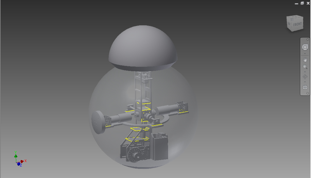
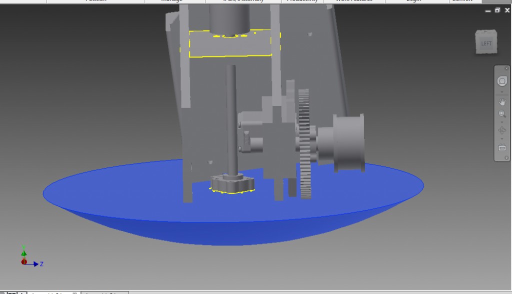
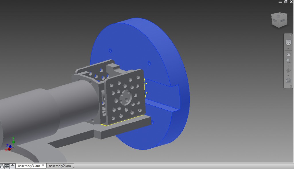
Once you build that system and install it it will look like this if you use the Bearing system.
Now there ya go. Its the basic setup I am using in my BB droid. Again this guide it only a guide to help you guys, it is NOT guaranteed instructions! You will still need to do some engineering and modding to make this work. I am still working on things every day to perfect it! I hope this helps everyone.