Rss

  • twitter
  • youtube

Archives for : Arduino

DIY Keypad Entry for JEEP Wrangler


So I went to a river this weekend for a swim and realized that I had no way to lock my jeep up without hiding my key through my back soft window and fetching it after to unlock the Jeep, and if I can do that, so can anyone that was watching me hide my key! Then my friend showed me how his “super cool SUV” had a keypad for keyless entry. I told him that I would add that feature tomorrow, and I did, and here is how it looks!

I had some spare water tight keypads laying around from some old projects I did, So I took one, hooked it up to a microcontroller (called a arduino) along with my spare key I got when I bought the Jeep and began writing some code. Basically what the micro controller does it watch the keypad, and if the right code is typed it will push the unlock button twice on the factory key (so it unlocks all the doors, not just the driver). This will also deactivate the alarm as well. Then when your done, you can push the arrow button to lock the Jeep back up. It works great and I did not ruin my factory key. I can still unsolder the wires and use it just like from factory if I ever needed. The Key is well hidden and locked up so no one can find it and use it to drive my Jeep away. I love this and wanted to share!

0-1

Arc Reactor Proposal


This is by far one of more more fun projects Ive ever done! A little background first, my girlfriend, now fiancé, has always loved projects I’ve made and really enjoys them. She has started calling me Tony Stark (which any guy will gladly accept that comparison)  after I created a simple Arc Reactor prop replica to sit on display on my desk. So I had a idea after I decided to pop the question! How great would it be if my “Arc Reactor Heart” could give her the ring? So the idea was created!

So I went off and started redesigning the reactor. I made it smaller, and more detailed. I laser cut and cnc routed all of the parts and slowly starting building the basic shell.  My idea was to use two servos controlled by and arduino. At first I was not sure how to light it up, but I had some of AdaFruit’s RGB LED Strip laying around from a pinball project. So I cut off enough to go around the reactor and used the arduino to control that as well! Also added a couple of bright white LEDs to hit the ring once it comes out. So here is the inside of the device.

photo 2 copy 2 photo 1 copy 2

The two halves screw together and hookup easily. I had to keep everything very compact so the servos would not hit each other. Also had to come up with a small bracket to hold the ring, but allowed it to easily be pulled off and put back on as you can see in the second picture. So needless to say, she said yes and loved the ring and the reactor! Hope you all enjoyed and it gave you ideas for your own projects!

NBA Hangtime Pinball Backglass COMPLETE


Well.. The Home Made Hangtime Pinball project is coming farther! Today, I finished the back glass and scoreboard system. The whole scoreboard system was made from scratch with 10mm and 5mm LEDs with Shift Registers and Transistors. Its running really nice and thought to share it all with you! It really is a treat seeing this project come to life! Here is the video!


Its really nice to have the pinball cab already in place, I will be painting over those tutles soon, even though I feel like im sinning! But what a better way to bring an old pinball to life than reincarnating it into a homemade pinball!!

The artwork changed a bit, here is the actual print!

I really wanted this pinball to stand out among the rest. This is why I not only have a pinball DMD (well kinda) display, but thought an old school point counter system would be retro and cool! So my mission was to include a basketball scoreboard into the back glass artwork, and I must say it came out better than I expected. I built the whole thing out of LEDs and Shift Registers basically. As you can see in the pictures below, there are a few different “modules”. They all connect together over ribbon cable, which includes the latch, clock and data for the shift registers, plus a couple of grounds, +5v and +12v. The Arduino Mega is what is controlling all of these along with sending signals for the other arduinos that take care of the other functions, like audio and the DMD (check out my other posts for details on those).

Alot of mess, but it does all make sense. These are for the scoring system of the scoreboard. These are essentially 7-segment LED Displays made out of 10mm orange LEDs.  Its hard to see, but each board has a 10-pin IN and OUT ribbon cable connection to run the shift registers, ground and power. I then needed to create the Period, Possession, Overtime and shotclock LEDs. Which is below.

Again, the shotclock is basically 7 segment LEDs, but this one out of 5mm Red LEDs. Then the est are more 10mm Orange LEDs, the 4 shift registers power all of these. Some may say you could get away using less shift registers since there are unused pins (especially on the third digit of the player scores) but they are cheap enough, that using them like this made it much easier to program and looks cleaner. This board again has the 10-pin IN and OUT on the back to link with the player scores.

Next I needed to recreate the backlight wood door. I like using actual bulbs instead of a fluorescent light or LEDs becuase it gives it a more retro, real pinball feel.

These lights are controlled by a lighting board, that uses shift registers and mosfets. This board gets its commands over I2C so it can work while the other things are going on. You can see this board in the pictures of the inside, and it will be upgraded with much more MOSFETs and transistors soon. So after installing this, and getting all of the LEDs aligned with the artwork, it looked like this.

Looks great to me! To really see it in action, check out the video at the top of the page!

Here is also a glance at the inside. After I finish getting it all organized and finished, I will do another post, with more details.

NBA Hangtime Pinball LED Screen Test

Next update on the NBA Hangtime Pinball is the LED screen. I have been wanting to make this for quite sometime. I am using 4 Sure 2416 LED Matrix boards and they are using an arduino Uno for communication at the time (It will get a standalone Mega after I finish the programming). The code for these boards are available all over the web, and I will post mine once I finish it becuase it is a mess right now. I am using the Arduino Mega as my master cpu and it is sending commands via I2C to this screen (check my blog on the sound boards for more information). So as you can see in the video below, it is running the LED screen and all the sound at the same time! I am getting closer! It can display small, large and graphic fonts and is running smooth as of now. Now I just need to work hard on making it look better and run smoother, which always seems to be the hard part……….


Multi-Tasking Arduino Pinball Audio


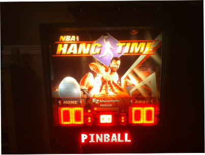
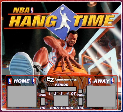
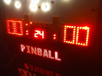
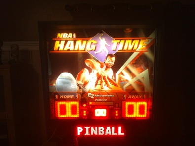
Well, another project has already consumed some of my time. I have decided to do a large project that will take up alot of time and would be a great learning experience. I have decided to make a pinball machine! And what a great theme, NBA Hangtime! I use to play this game growing up and still do, I even have a MAME machine sitting inside a Hangtime Cabinet. What makes the game excellent are many things, like the dunks, the minimal rules, 2 on 2, and who can forget the audio??? “Ooohhhhhhhhhh… BOOM Shaka Laka!”. Well I thought that the audio board would be the first thing to do, since it would make or break this machine. I am very pleased with the outcome!

Parts I used:

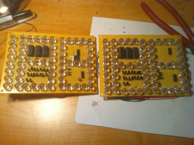
3 – Arduino WaveShields

3 – ATMega328 with Arduino Bootloader

3 – SD Cards

  1. Misc parts for the ATMegas (Read this for standalone ATMegas)

  2. Arduino Mega 2560 (Any will work, it sends the commands)

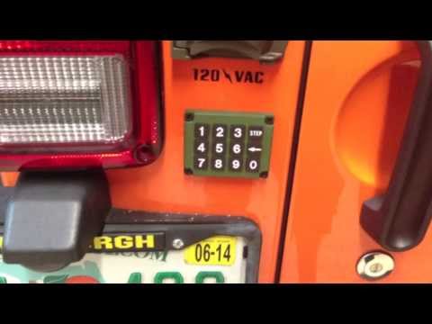
I recommend reading up on the I2C protocol if you do not understand it, it is VERY useful! (HERE)

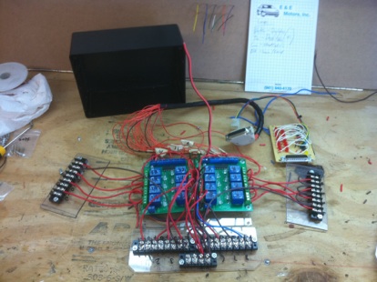
So, one of the main problems people have with ATMegas are the fact you can not do multiprocessing, so in this example, if your playing a sound, you can not play another suond till that first sound is over. This is pretty much unacceptable for pinball machines. You have background music, and other effects happening all at once. So this is where the amazing I2C protocol comes in to help. It allows you to hook up many ATMegas taht can talk to each other. This allows you to have a Master sending commands to other arduinos so that they do the processing while the master goes onto other things… Soo.. Multiprocessing! (some micro-controllers can do this themselves, like the Parallax Propeller, it has 8 cogs, which are separate processors, but I wanted to do everything with Megas, since I understand the code, and its a challenge!)

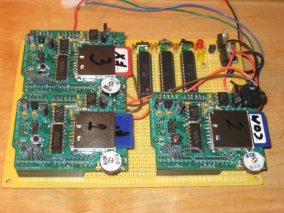
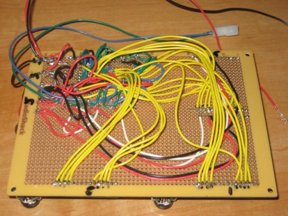
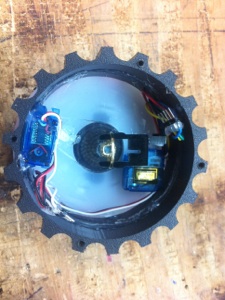
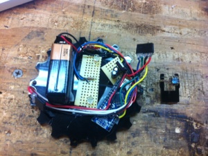
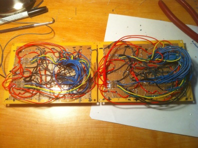
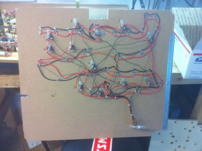
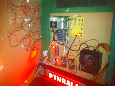
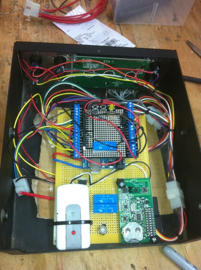
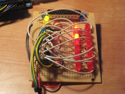
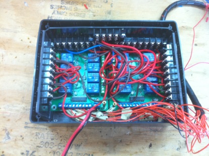
In this last picture you can see the horrible ammount of wiring I had to do to get it all to work. But what i want you to look at is those Blue and Green wires coming from that molex connector. These are the I2C lines. They are just daisy chained from one mega to the other. If you look at my code, i send them commands based on what is happening. Each Mega has a separate address, in this case, they are 1, 2 and 3. So I send this command from the master…

sendcom(11, 27);

void sendcom (byte x, byte y) {

    Wire.beginTransmission(2); // transmit to device #2

  Wire.send(1);        //sends a command to tell it is “On”

  Wire.send(x);        // sends directory number

  Wire.send(y);       //sends file number, or “random number”

  Wire.endTransmission();    // stop transmitting

}

Then the slave arduino #2 gets 3 bytes. It recieves..

(1, 11, 27)

So it takes those and plays a file off the card (check the waveshield website for more info on that)

1 means its on, then it looks at the 11 (which on the SD card is the files in the 1100s, like 1101, 1125, 1131) and then it sees the 27 which is file 27…. in the 1100s…. so file “1127.wav”. The reason for this is I have some math that allows me to do random plays. It is constantly adding the int “randomnumber” by 1 till it hits 51, then tells it to go back to 0. That way when I use “randomnumber” like…

sendcom(11, randomnumber);


it will tell the slave to play a random file in the 1100s. This works great when playing pinball to keep things fresh. There is ALOT of possible combinations with this!


Getting all of the audio was very very time consuming. I used a program called M1. It dissects the game rom file and I could extract all the tracks. This took a very long time and I ended up with hundreds of sounds, commentator sayings and music. Now I have all of that organized and can make my own audio on the fly. Way Way Way better than trying to record the audio in game, it would have horrible background sounds and whatnot. I probably wouldve given up on the idea if I didnt find that M1 program and got all the sounds by themselves.


HERE is the M1 Program.


Source Codes:


master.txt

slave.txt


I am still working on the code and the way it will all work. This is going to be a LONG project, and im sure ill have other projects in the middle of it, but it will get done eventually. If you have ANY ideas for the machine, please email me, let me know what you got! Represent NBA HANGTIME LOVE!


Arduino Powered JEEP Wrangler

This has been a long process in the making. I started with this idea awhile ago and tried out different ways to program microcontrollers. I first started with one of the “NerdKits”. Now this was a good kit, but when you were done with there tutorials, there wasn’t much more to do. I then went with the Arduino and I wish I would’ve started there! It is excellent for the beginner and pro. So this is my first arduino project and my first time really programming anything except HTML. So check out the video, then read on.

Before I used an arduino to control everything, I used actually switches as you can see in this picture

But this was definitely not good enough as I wanted to add more things and its just to easy. So the challenge was to make the JEEPuter. I first started out making it on a breadboard (i dont have pics of this) But after I had the basic idea in my head with a somewhat working prototype, I started building the housing for it. I used sheet metal and plexi for the faceplate. Along with using some label paper to make the art work (if you could call it that)

I used some basic Radio Shack momentary buttons and a 20×4 LCD display. It looks really good behind the plexiglass front of the faceplate. All of the connections hook up threw molex connectors to make it easy to work on. The random cuts in the plate are to make it fit in the tuffy overhead mount easier. It doesnt looks as ugly when installed as you can see here.

I used a Arduino Uno and left the whole board in there instead of making a standalone board so I could program it easier. The arduino is outputting all of the “outs” to 3 shift registers. One register is inside of the JEEPuter box, the other two are on there own board that is installed inside the relay box. Here in this picture you can see the Arduino with a screw shield above it with 3 relays. Two control the garage door opener and RF Garage Lights. The other is actually turnign power on to the shift registers. Reason for this is when the arduino boots up, the registers all go high. This is an issue when you have a starter hooked up to them.

Then the other two registers are on this board. This board I made specifically as the control board for the relays. It has two 595 Shift Registers along with 16 LEDs. Each LED represents an output coming from the registers. THis made it easy to program without hooking up all the relays and helps to troubleshoot. This board has  a 25 pin connection on it that outputs to each and every relay.
And then I had a breakout cable go from the 25 pin output to all of the relays. I only used 20 pins, 16 outputs, 2 grounds, 2 5v+. These go to each relay on theses relay boards I purchased on ebay. I could have made my own, but this was easier and better to have printed PCB for this.

The relays were then put inside a project box from radioshack. This helped insulate them from shorting out on the jeep and kept it all in one place. I used plexi and screw terminals to make hooking up easier. This was a bit difficult to get it all to fit as you can see in these next shots.

I then installed the shift registers board inside and added a fan to keep it cool.

There are also a couple of sensors hooked up that you can see in action in the top video. There is a Light sensor, Temp sensor and a RTC. (I may add a carbon monoxide sensor). the Light sensor value is brought into the arduino and divided by 20, then that number is used to turn off and on lights depending if its dark outside. (this is also selectable per light). You can change the sensitivity in the diagnostics mode. It allows you to tell when to turn lights on and light off. This gives you a dead zone so the lights don’t flicker when you get close to dark but still light out. These numbers will be saved in the EEPROM of the arduino. The Temp sensor just outputs F and C on the display. The RTC provides the time and date and you can change if its either Daylight savings time or not in the diagnostics. This helps so you don’t have to set the clock twice a year.

I also added another arduino (standalone)  that had a keypad attached to it with a couple relays that control turning on the power to the jeep and ignition if you type the code in it. So this gives you the ability to not need a key to use your jeep, only a code.

When you type in the code, it turns the Jeep on as if you turned your key to the “On” position. This then turns on all the accessories as well. There Starting of the engine is done threw the arduino JEEPuter uptop. The original key still works perfectly fine. To turn the Jeep off, you just hit the <– button on the keypad, and it shuts down. Check out the pictures to see the arduino setup for the keypad.

Download Source Code  <—- Its not pretty, its my first!