Rss

  • twitter
  • youtube

Archives for : Mods n Hacks

Captain America XBOOK vs Iron Man PLAYBOOK

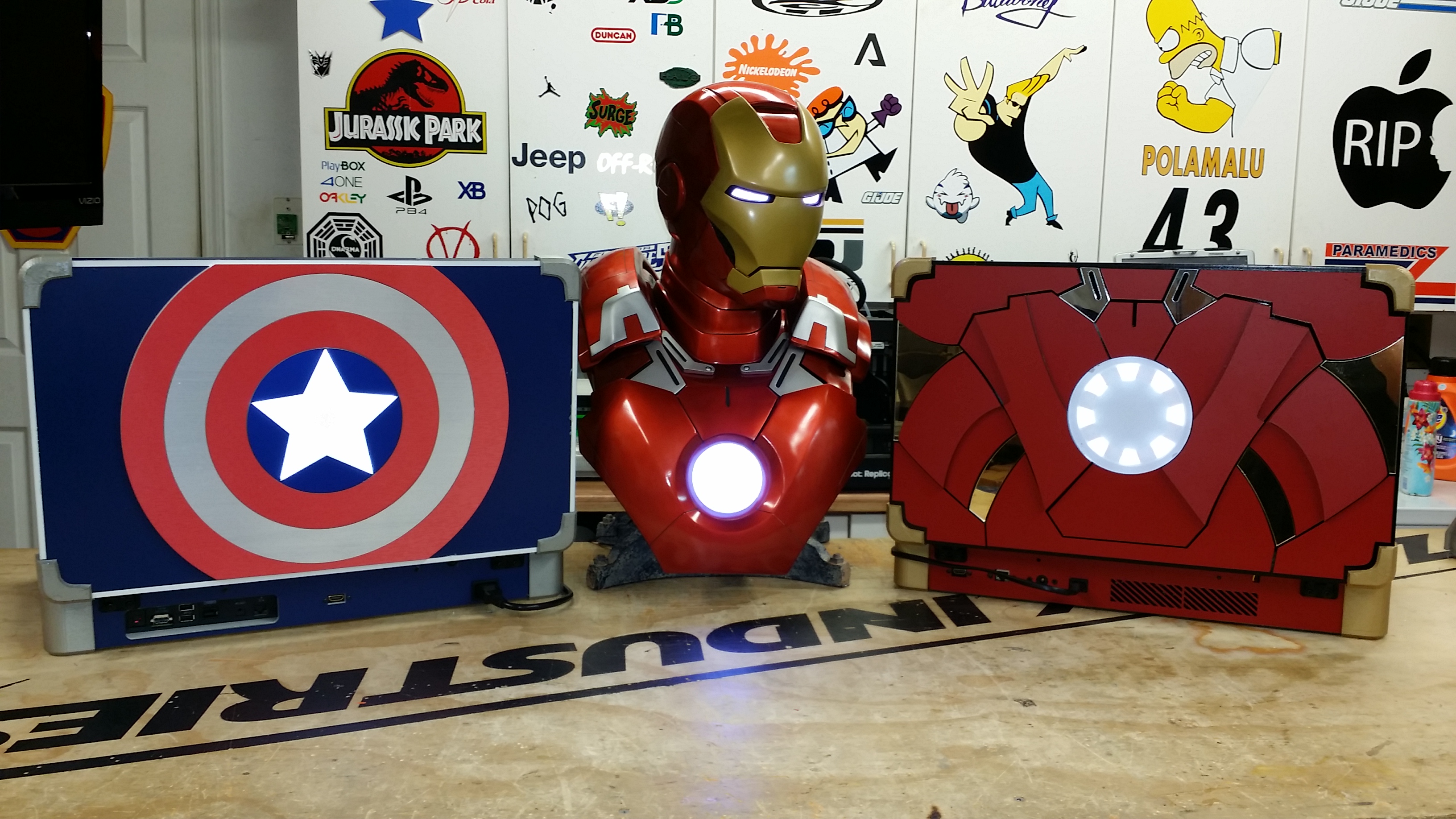
Well Guys I am back at it yet again! Today we we have a special edition for both systems! Captain America XBOOK ONE and a Iron Man PLAYBOOK 4. This is a great duo with the Captain America Civil War movie coming up next year. These systems both boast their own unique designs and features, along with the standard specs you have seen in my previous systems. Lets check them out!


Each system obviously looks different! They each are themed after the characters they resemble. You have the Captain America XBOOK ONE which has his Captain Rogers shield along with his uniform design and American colors. Then next to that you are looking at a Gold and hot rod Red Iron Man PLAYBOOK 4 which includes his armor, Arc Reactor and even Jarvis HUD on the inside.

First up lets look at the Captain America XBOOX ONE and see what else it has to offer.

IMG_0656

IMG_0665


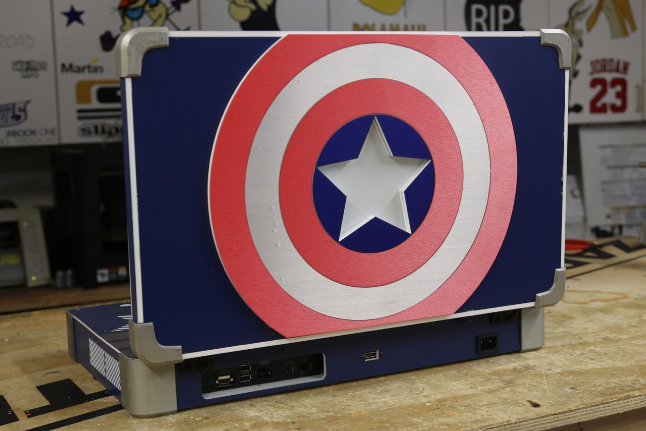
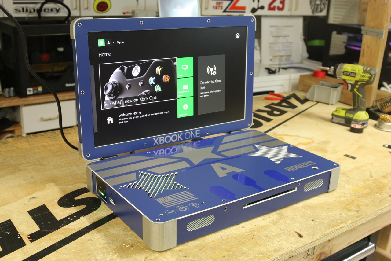
Not only does this system looks cool, it also has a couple unique features that I have only incorporated into this specific XBOOK. First off is design. The shield on the back of the system is using a brushed metal vinyl work on top of acrylic to give the shield depth and the illusion of metal. The star in the middle of the shield lights up when the XBOX is turned on and really does look stunning in person. The inside goes with Captain’s uniform utilizing the middle silver star with accents around it. Seeing as the system needs to vent, it only seemed appropriate to use stars as the vents, so those were brought into the design. Now what makes this system unique you ask other than some decal work? Well it has a built in HD Capture card!

IMG_0659


Thumbnail


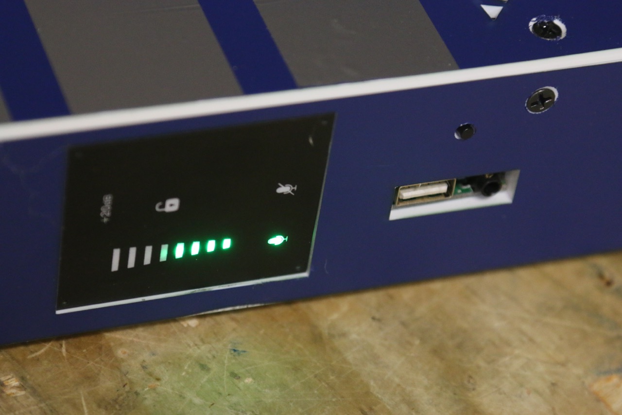
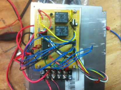
A Hauppauge HD PVR Rocket was installed into this system permanently. As you can see from the photo, all of the touch sensors and buttons are still accessible through the side of the unit. All you need to do is plug in a USB stick and a mic (if you want to narrate) and begin recording your session! This system records directly onto the USB stick, so all you need to do is plug it into your computer when your done, and your good to go! This is something I have been wanting to do for awhile and thought the Captain deserved such a mod!


Now Lets see how Iron Man stacks up against the Cap!

IMG_0646

IMG_0647

IMG_0648

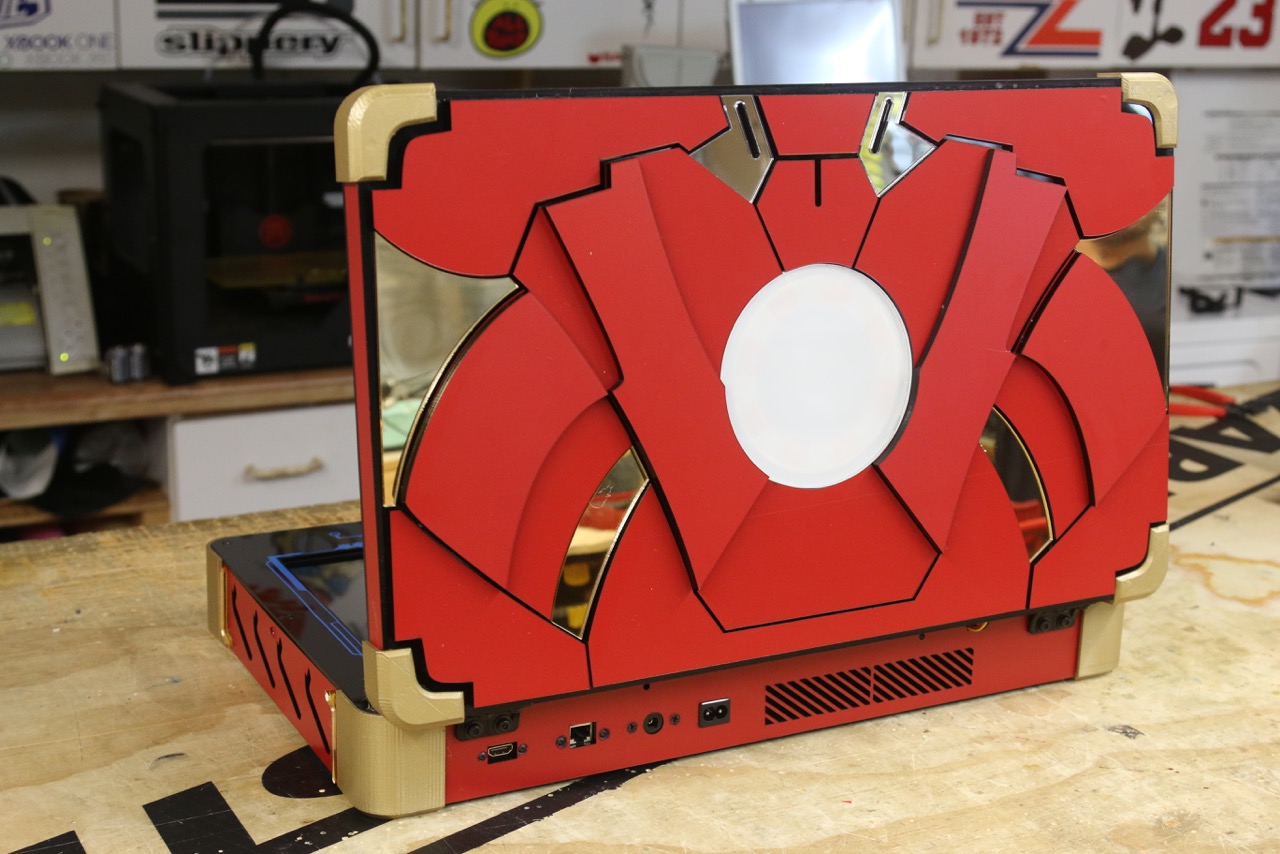
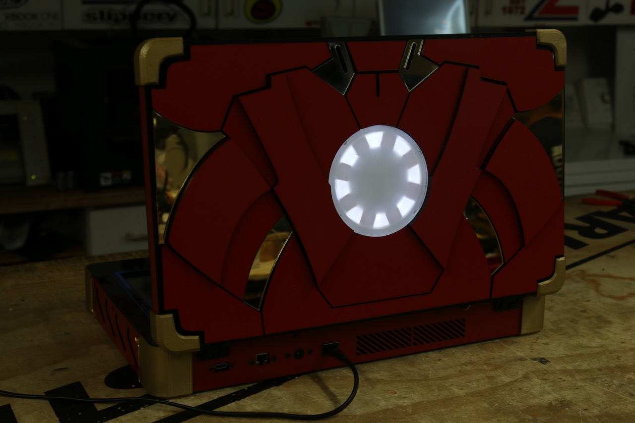
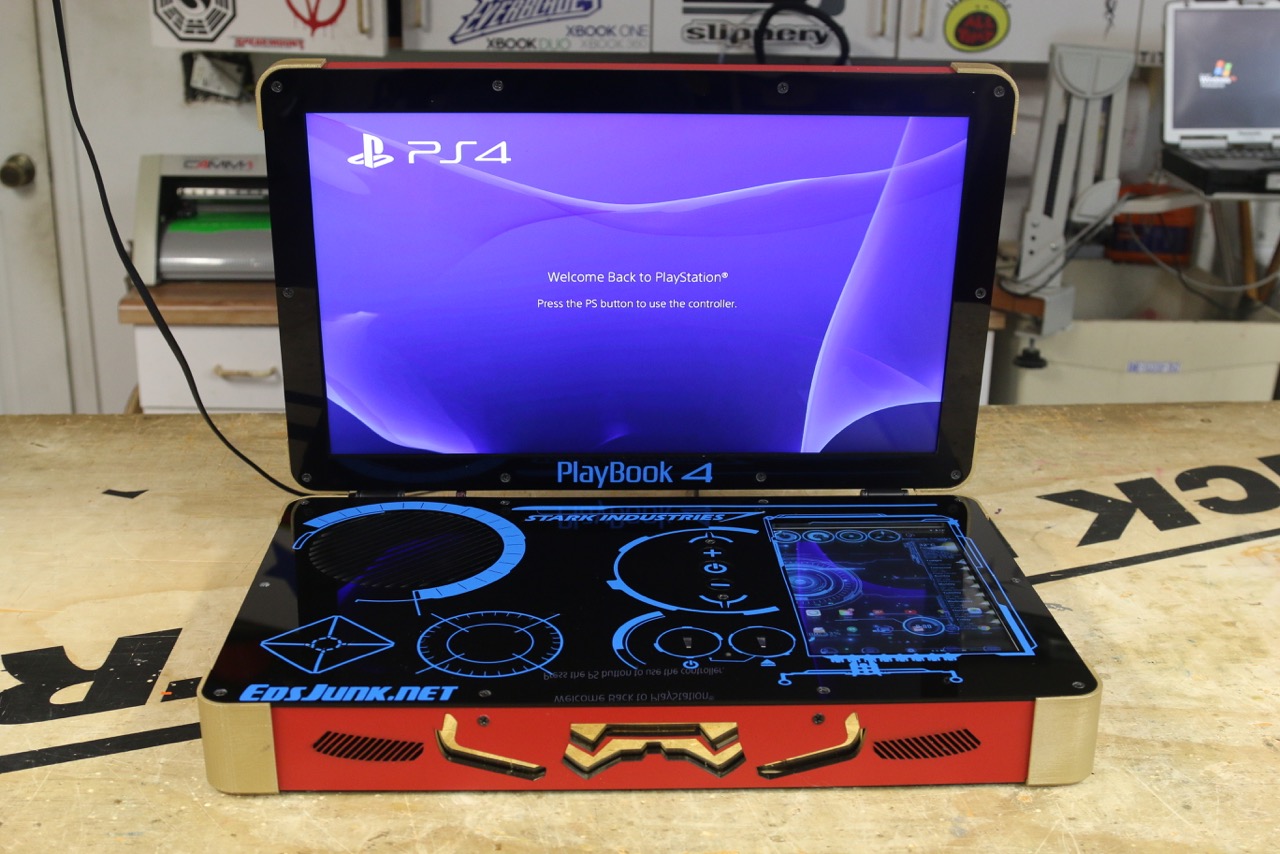
If you don’t recognize Iron Man in this system, I do not know what will! This system was built from the ground up with Tony Stark in mind! I thought, when Tony is not working on his next Mk for a Iron Man and he wants to game… It has got to be through a PLAYBOOK 4 that looks like this! Clearly the only way to power such a beast of a system is to give it its own Arc Reactor centered in Iron Man Armor. This arc reactor lights up whenever the system is powered and gives it a great look! The otter shell is composed of Hot Rod Red Armor and Gold trim work, just to Mr Starks specs. Now when you think of what is inside Iron Man, the only logical answer is JARVIS. What is Iron Man without JARVIS?! The inside is made up Black Acrylic with Blue H.U.D. accents. Now what this system has that is unique to any other PLAYBOOK is a built in Android as a secondary screen!

IMG_0650

IMG_0649


ironman3_Hud_Design


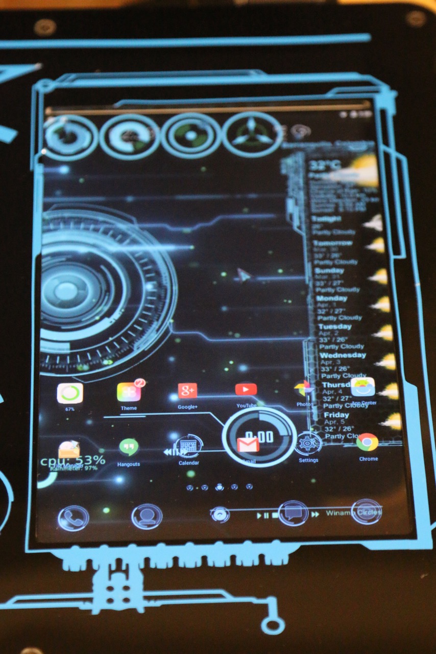
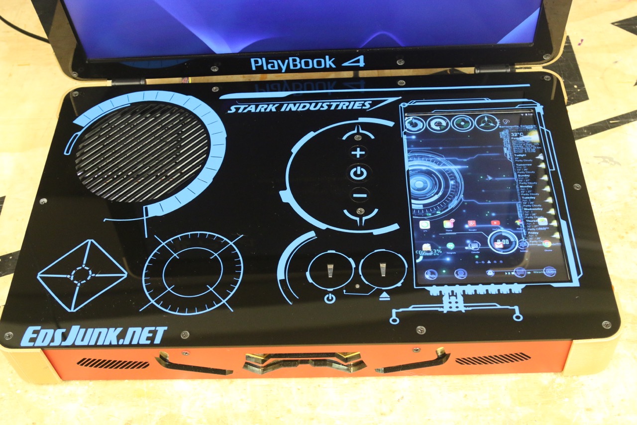
This Android is a 10″ screen and is not there only for looks… it has function! When the PS4 teams up with Android and PS4 App, they make quite the pair! You have the ability to control the PS4 directly from the touch screen, eliminating the need for a controller if say you only wanted to watch a movie. Also while playing a game, you can check you PSN updates, messages and notifications without leaving your game.. just look down at the second screen and your done! The Android will also act as a keyboard for when you need to input text into a game. Much easier than using the controller! It can also function as a normal android as well, allowing you to check your email, search the web for a walk though guide to the game, or play music! The Android charger is also built in, so when the system is on, the android is on! Pretty slick, and I don’t think Tony would have it any other way!

Also a small, but cool feature to this system, is when you plug it in, you are greeted with a JARVIS voice and he lets you know when your preferences are done uploading and your online and ready! Check out the youtube Video to see it in action!


2015-09-07 16.01.17

All in All these two systems and super unique and some of my best work to date. I wanted to top myself and do something different, but useful. I believe both systems has something for everyone and really are one of a kind items. These are not systems I plan on ever making again and was a one time deal. They took me MUCH longer than my standard systems to make and really show off their features.

If you are interested in purchasing a XBOOK or PLAYBOOK please check out www.xbookone.com or www.playbook4.com for more information!

FLIR Thermal Night Vision on Jeep Wrangler

Here is something I wanted to do for awhile on my Jeep Wrangler. It is FLIR Thermal Night Vision. Check out the video. I explain what I did to create this nifty gadget

0

I used a old Cadillac “Night Vision” Camera that use to come on some of there models from 01-05. It truly is a Thermal “FLIR” Camera, not so much Night Vision, but has a similar purpose. This is the same technology used on Apache Helicopters and other military vehicles to spot the enemy at night since there heat is what the camera picks up.I mounted this camera to a GoLight Moveable spot light after removing the bulb and lens. I thought the camera would be smaller than it is and I would be able to mount it inside the GoLight, but it had to be mounted to the outside the still be able to get some up and down movement. The camera video feed is wired directly into my Jeeps Stereo head unit and can display the feed whenever it is selected. The joy stick is mounted directly below the head unit and has a great range of motion (would have a lot more if mounted ontop of the jeep). I turn the camera towards the grill when not in use to protect the lens from debris. Overall I accomplished my goal to have a moveable FLIR camera on my Jeep and I am happy with the results. I will be finding a different system to move the camera to replace to GoLight so that it all fits better and looks a little cleaner.

DIY Keypad Entry for JEEP Wrangler


So I went to a river this weekend for a swim and realized that I had no way to lock my jeep up without hiding my key through my back soft window and fetching it after to unlock the Jeep, and if I can do that, so can anyone that was watching me hide my key! Then my friend showed me how his “super cool SUV” had a keypad for keyless entry. I told him that I would add that feature tomorrow, and I did, and here is how it looks!

I had some spare water tight keypads laying around from some old projects I did, So I took one, hooked it up to a microcontroller (called a arduino) along with my spare key I got when I bought the Jeep and began writing some code. Basically what the micro controller does it watch the keypad, and if the right code is typed it will push the unlock button twice on the factory key (so it unlocks all the doors, not just the driver). This will also deactivate the alarm as well. Then when your done, you can push the arrow button to lock the Jeep back up. It works great and I did not ruin my factory key. I can still unsolder the wires and use it just like from factory if I ever needed. The Key is well hidden and locked up so no one can find it and use it to drive my Jeep away. I love this and wanted to share!

0-1

Walk-around of my Jeep

Watch this video to see it all. Its just a walkthrough of all the mods I have done to my Jeep. Its a good quick overview and I try to explain as much as I can.

Running Pressurized Water on JEEP Wrangler


Well a few weeks ago I figured out that the rear stock bumper will hold water very well. At first I thought it would hold 10 gallons, but looks like it is more like 7. Still more than the AEV Bumper! Anyways, i wanted to use that water as running water to hose off my jeep and me after mudding, hose down my scuba gear after diving, washing hands, ext. So Here is how I did it!


First, you need to seal your bumper. On a stock bumper there is 4 drain holes on the bottom to seal. For now, i just plugged them with stainless bolts. 


Then you need to drill a couple holes onto the top, I put one on the drivers side to fill the tank with a cap. The other side I hid between the fender and bumper, this is the pickup line, and is great here since you can not see it at all! I use a pvc pipe since it is rigid and sealed it well.


After this, I designed my outlet for the water to come out. I am going to be putting in a air compressor in the near future, so I went ahead and designed a panel that would handle both. I used a normal hose spickett so you can have multiple hook up uses. I have some cnc equipment, so I designed a nice panel and gasket to keep a good seal. 


Now, came the part that made me a little nervous, I needed to cut into the side of my jeep to hide all of the lines, but yet make it look cool and unique. So Here is where I cut the side of my jeep. Is is nice, because there is a lot of room behind here not being used and allows you to run your hoses outside the jeep and underneith it without drilling any more holes. You can run the hose up and over and it will drop behind your fender under the jeep. see pics.


I know I know, how could I do this! But, its no different then when you need to cut your hood for a PS Hood louver! (which I am getting from UPS today!) After cutting, make sure you paint any exposed metal to reduce rust in the future! I then installed my panel with its gasket, and it came out very nice!


The pump I used is a shurflo pump used on RVs. Mine gets about 3.2 gallons per minute at 55 PSI. What is nifty about these little pumps is that they automatically turn off when the pressure reaches 45 PSI. So what that means is you don’t need an extra on/off switch for your water. Whenever you open the nozzle/spicket, the water comes out, reducing pressure slightly, the pump sees this and turns on. Then when you close it it sees the pressure build up, and turns off! cool trick! It also self primes itself and can run dry without damage (will turn it self off automatically after dry for a few) I mounted the pump underneath the jeep above and to the side of the rear diff. There was a lot of extra space up there and it wont be hit. The lines hooked up to it and ran power straight to the battery.


You will need to get different fittings ext depending on the way you set yours up, but this is a general idea and gives you the idea to go out and do it! Check out both videos, it shows it all installed and working with a hose and the other shows it all setup before it was installed!


Arc Reactor Proposal


This is by far one of more more fun projects Ive ever done! A little background first, my girlfriend, now fiancé, has always loved projects I’ve made and really enjoys them. She has started calling me Tony Stark (which any guy will gladly accept that comparison)  after I created a simple Arc Reactor prop replica to sit on display on my desk. So I had a idea after I decided to pop the question! How great would it be if my “Arc Reactor Heart” could give her the ring? So the idea was created!

So I went off and started redesigning the reactor. I made it smaller, and more detailed. I laser cut and cnc routed all of the parts and slowly starting building the basic shell.  My idea was to use two servos controlled by and arduino. At first I was not sure how to light it up, but I had some of AdaFruit’s RGB LED Strip laying around from a pinball project. So I cut off enough to go around the reactor and used the arduino to control that as well! Also added a couple of bright white LEDs to hit the ring once it comes out. So here is the inside of the device.

photo 2 copy 2 photo 1 copy 2

The two halves screw together and hookup easily. I had to keep everything very compact so the servos would not hit each other. Also had to come up with a small bracket to hold the ring, but allowed it to easily be pulled off and put back on as you can see in the second picture. So needless to say, she said yes and loved the ring and the reactor! Hope you all enjoyed and it gave you ideas for your own projects!

NBA Hangtime Pinball Backglass COMPLETE


Well.. The Home Made Hangtime Pinball project is coming farther! Today, I finished the back glass and scoreboard system. The whole scoreboard system was made from scratch with 10mm and 5mm LEDs with Shift Registers and Transistors. Its running really nice and thought to share it all with you! It really is a treat seeing this project come to life! Here is the video!


Its really nice to have the pinball cab already in place, I will be painting over those tutles soon, even though I feel like im sinning! But what a better way to bring an old pinball to life than reincarnating it into a homemade pinball!!

The artwork changed a bit, here is the actual print!

I really wanted this pinball to stand out among the rest. This is why I not only have a pinball DMD (well kinda) display, but thought an old school point counter system would be retro and cool! So my mission was to include a basketball scoreboard into the back glass artwork, and I must say it came out better than I expected. I built the whole thing out of LEDs and Shift Registers basically. As you can see in the pictures below, there are a few different “modules”. They all connect together over ribbon cable, which includes the latch, clock and data for the shift registers, plus a couple of grounds, +5v and +12v. The Arduino Mega is what is controlling all of these along with sending signals for the other arduinos that take care of the other functions, like audio and the DMD (check out my other posts for details on those).

Alot of mess, but it does all make sense. These are for the scoring system of the scoreboard. These are essentially 7-segment LED Displays made out of 10mm orange LEDs.  Its hard to see, but each board has a 10-pin IN and OUT ribbon cable connection to run the shift registers, ground and power. I then needed to create the Period, Possession, Overtime and shotclock LEDs. Which is below.

Again, the shotclock is basically 7 segment LEDs, but this one out of 5mm Red LEDs. Then the est are more 10mm Orange LEDs, the 4 shift registers power all of these. Some may say you could get away using less shift registers since there are unused pins (especially on the third digit of the player scores) but they are cheap enough, that using them like this made it much easier to program and looks cleaner. This board again has the 10-pin IN and OUT on the back to link with the player scores.

Next I needed to recreate the backlight wood door. I like using actual bulbs instead of a fluorescent light or LEDs becuase it gives it a more retro, real pinball feel.

These lights are controlled by a lighting board, that uses shift registers and mosfets. This board gets its commands over I2C so it can work while the other things are going on. You can see this board in the pictures of the inside, and it will be upgraded with much more MOSFETs and transistors soon. So after installing this, and getting all of the LEDs aligned with the artwork, it looked like this.

Looks great to me! To really see it in action, check out the video at the top of the page!

Here is also a glance at the inside. After I finish getting it all organized and finished, I will do another post, with more details.

NBA Hangtime Pinball LED Screen Test

Next update on the NBA Hangtime Pinball is the LED screen. I have been wanting to make this for quite sometime. I am using 4 Sure 2416 LED Matrix boards and they are using an arduino Uno for communication at the time (It will get a standalone Mega after I finish the programming). The code for these boards are available all over the web, and I will post mine once I finish it becuase it is a mess right now. I am using the Arduino Mega as my master cpu and it is sending commands via I2C to this screen (check my blog on the sound boards for more information). So as you can see in the video below, it is running the LED screen and all the sound at the same time! I am getting closer! It can display small, large and graphic fonts and is running smooth as of now. Now I just need to work hard on making it look better and run smoother, which always seems to be the hard part……….


Multi-Tasking Arduino Pinball Audio


Well, another project has already consumed some of my time. I have decided to do a large project that will take up alot of time and would be a great learning experience. I have decided to make a pinball machine! And what a great theme, NBA Hangtime! I use to play this game growing up and still do, I even have a MAME machine sitting inside a Hangtime Cabinet. What makes the game excellent are many things, like the dunks, the minimal rules, 2 on 2, and who can forget the audio??? “Ooohhhhhhhhhh… BOOM Shaka Laka!”. Well I thought that the audio board would be the first thing to do, since it would make or break this machine. I am very pleased with the outcome!

Parts I used:

3 – Arduino WaveShields

3 – ATMega328 with Arduino Bootloader

3 – SD Cards

  1. Misc parts for the ATMegas (Read this for standalone ATMegas)

  2. Arduino Mega 2560 (Any will work, it sends the commands)

I recommend reading up on the I2C protocol if you do not understand it, it is VERY useful! (HERE)

So, one of the main problems people have with ATMegas are the fact you can not do multiprocessing, so in this example, if your playing a sound, you can not play another suond till that first sound is over. This is pretty much unacceptable for pinball machines. You have background music, and other effects happening all at once. So this is where the amazing I2C protocol comes in to help. It allows you to hook up many ATMegas taht can talk to each other. This allows you to have a Master sending commands to other arduinos so that they do the processing while the master goes onto other things… Soo.. Multiprocessing! (some micro-controllers can do this themselves, like the Parallax Propeller, it has 8 cogs, which are separate processors, but I wanted to do everything with Megas, since I understand the code, and its a challenge!)

In this last picture you can see the horrible ammount of wiring I had to do to get it all to work. But what i want you to look at is those Blue and Green wires coming from that molex connector. These are the I2C lines. They are just daisy chained from one mega to the other. If you look at my code, i send them commands based on what is happening. Each Mega has a separate address, in this case, they are 1, 2 and 3. So I send this command from the master…

sendcom(11, 27);

void sendcom (byte x, byte y) {

    Wire.beginTransmission(2); // transmit to device #2

  Wire.send(1);        //sends a command to tell it is “On”

  Wire.send(x);        // sends directory number

  Wire.send(y);       //sends file number, or “random number”

  Wire.endTransmission();    // stop transmitting

}

Then the slave arduino #2 gets 3 bytes. It recieves..

(1, 11, 27)

So it takes those and plays a file off the card (check the waveshield website for more info on that)

1 means its on, then it looks at the 11 (which on the SD card is the files in the 1100s, like 1101, 1125, 1131) and then it sees the 27 which is file 27…. in the 1100s…. so file “1127.wav”. The reason for this is I have some math that allows me to do random plays. It is constantly adding the int “randomnumber” by 1 till it hits 51, then tells it to go back to 0. That way when I use “randomnumber” like…

sendcom(11, randomnumber);


it will tell the slave to play a random file in the 1100s. This works great when playing pinball to keep things fresh. There is ALOT of possible combinations with this!


Getting all of the audio was very very time consuming. I used a program called M1. It dissects the game rom file and I could extract all the tracks. This took a very long time and I ended up with hundreds of sounds, commentator sayings and music. Now I have all of that organized and can make my own audio on the fly. Way Way Way better than trying to record the audio in game, it would have horrible background sounds and whatnot. I probably wouldve given up on the idea if I didnt find that M1 program and got all the sounds by themselves.


HERE is the M1 Program.


Source Codes:


master.txt

slave.txt


I am still working on the code and the way it will all work. This is going to be a LONG project, and im sure ill have other projects in the middle of it, but it will get done eventually. If you have ANY ideas for the machine, please email me, let me know what you got! Represent NBA HANGTIME LOVE!


Arduino Powered JEEP Wrangler

This has been a long process in the making. I started with this idea awhile ago and tried out different ways to program microcontrollers. I first started with one of the “NerdKits”. Now this was a good kit, but when you were done with there tutorials, there wasn’t much more to do. I then went with the Arduino and I wish I would’ve started there! It is excellent for the beginner and pro. So this is my first arduino project and my first time really programming anything except HTML. So check out the video, then read on.

Before I used an arduino to control everything, I used actually switches as you can see in this picture

But this was definitely not good enough as I wanted to add more things and its just to easy. So the challenge was to make the JEEPuter. I first started out making it on a breadboard (i dont have pics of this) But after I had the basic idea in my head with a somewhat working prototype, I started building the housing for it. I used sheet metal and plexi for the faceplate. Along with using some label paper to make the art work (if you could call it that)

I used some basic Radio Shack momentary buttons and a 20×4 LCD display. It looks really good behind the plexiglass front of the faceplate. All of the connections hook up threw molex connectors to make it easy to work on. The random cuts in the plate are to make it fit in the tuffy overhead mount easier. It doesnt looks as ugly when installed as you can see here.

I used a Arduino Uno and left the whole board in there instead of making a standalone board so I could program it easier. The arduino is outputting all of the “outs” to 3 shift registers. One register is inside of the JEEPuter box, the other two are on there own board that is installed inside the relay box. Here in this picture you can see the Arduino with a screw shield above it with 3 relays. Two control the garage door opener and RF Garage Lights. The other is actually turnign power on to the shift registers. Reason for this is when the arduino boots up, the registers all go high. This is an issue when you have a starter hooked up to them.

Then the other two registers are on this board. This board I made specifically as the control board for the relays. It has two 595 Shift Registers along with 16 LEDs. Each LED represents an output coming from the registers. THis made it easy to program without hooking up all the relays and helps to troubleshoot. This board has  a 25 pin connection on it that outputs to each and every relay.
And then I had a breakout cable go from the 25 pin output to all of the relays. I only used 20 pins, 16 outputs, 2 grounds, 2 5v+. These go to each relay on theses relay boards I purchased on ebay. I could have made my own, but this was easier and better to have printed PCB for this.

The relays were then put inside a project box from radioshack. This helped insulate them from shorting out on the jeep and kept it all in one place. I used plexi and screw terminals to make hooking up easier. This was a bit difficult to get it all to fit as you can see in these next shots.

I then installed the shift registers board inside and added a fan to keep it cool.

There are also a couple of sensors hooked up that you can see in action in the top video. There is a Light sensor, Temp sensor and a RTC. (I may add a carbon monoxide sensor). the Light sensor value is brought into the arduino and divided by 20, then that number is used to turn off and on lights depending if its dark outside. (this is also selectable per light). You can change the sensitivity in the diagnostics mode. It allows you to tell when to turn lights on and light off. This gives you a dead zone so the lights don’t flicker when you get close to dark but still light out. These numbers will be saved in the EEPROM of the arduino. The Temp sensor just outputs F and C on the display. The RTC provides the time and date and you can change if its either Daylight savings time or not in the diagnostics. This helps so you don’t have to set the clock twice a year.

I also added another arduino (standalone)  that had a keypad attached to it with a couple relays that control turning on the power to the jeep and ignition if you type the code in it. So this gives you the ability to not need a key to use your jeep, only a code.

When you type in the code, it turns the Jeep on as if you turned your key to the “On” position. This then turns on all the accessories as well. There Starting of the engine is done threw the arduino JEEPuter uptop. The original key still works perfectly fine. To turn the Jeep off, you just hit the <– button on the keypad, and it shuts down. Check out the pictures to see the arduino setup for the keypad.

Download Source Code  <—- Its not pretty, its my first!